Sliding sun visor

a sun visor and sliding technology, applied in the direction of roofs, anti-glare equipment, superstructures, etc., can solve the problems of difficult sun visor design and extension of sun visors

Inactive Publication Date: 2006-06-01
GRP ANTOLIN ING SA
View PDF3 Cites 11 Cited by
  • Summary
  • Abstract
  • Description
  • Claims
  • Application Information

AI Technical Summary

Benefits of technology

[0027] Slide guiding. The tube or conductor housing means is both a cover for the conductor or flexible tape (FFC or FPC) and a guide for the slide. Thus, the tube drives sliding movement when the slide goes forward and backward to provide precise positioning and solid feeling when extending the sun visor.

Problems solved by technology

However, dimensions of the adjacent elements to the sun visor make difficult to design sun visors which do not interfere with the elements surrounding the sun visor.
An added problem to the extension of sun visors takes place when a vanity mirror with lightning is included in the sun visor.

Method used


Image

  • Sliding sun visor
  • Sliding sun visor
  • Sliding sun visor

Examples


Embodiment Construction

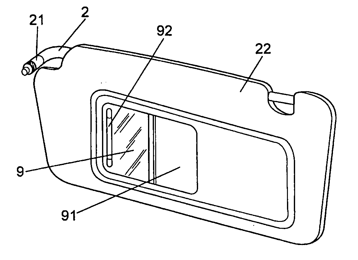
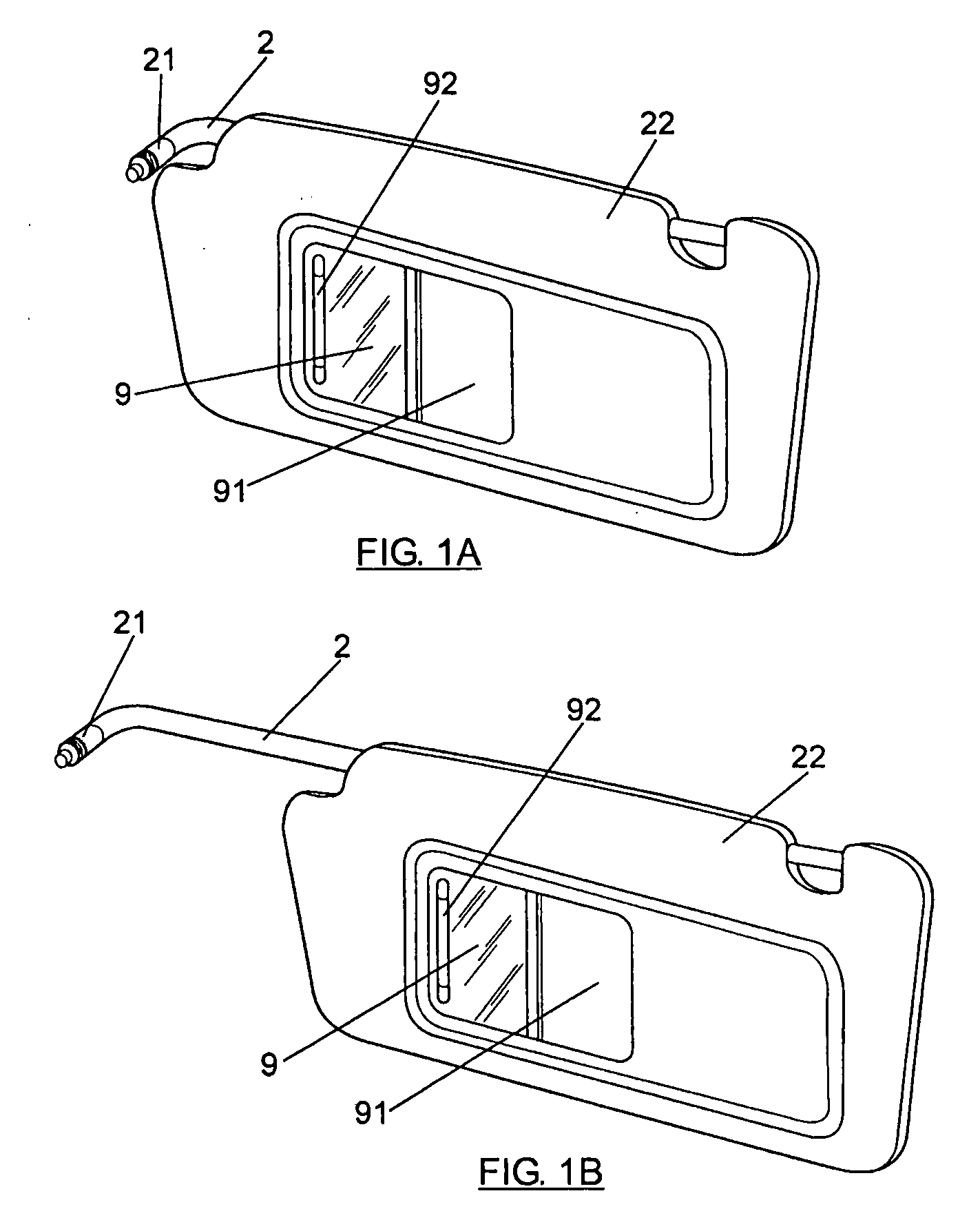
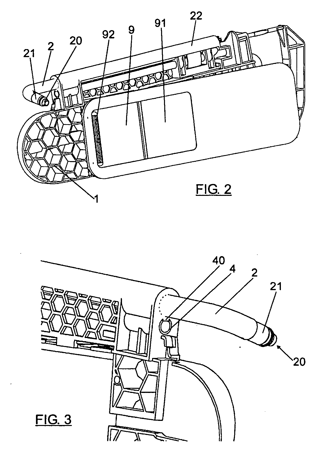
[0015] The present invention provides a sun visor with additional protection beyond its home position, guaranteeing power supply in every position: not extended, partially or totally extended.

[0016] The present invention comprises a plurality of features:

[0017] Slide with metal guide. Extension of the sun visor is carried out by sliding the pivot rod and slide or sliding guiding means, which are joint, in the racket or sun visor structure. The slide is guided by a metal tube or conductor housing means parallel to the pivot rod, said tobe being used as a housing of electrical lead or conductor.

[0018] Flexible tape of power supply or flexible printed circuit (FPC), in other words, the conductor. Power supply all along the sun visor length form the entry of the pivot rod to the mirror is carried out by means of a flexible tape conductor such as a type if flexible printed circuit (FPC) or flexible flat cable (FFC). Said flexible tape is capable of changing its shape in each movement ...


PUM


Abstract

A sliding sun visor having: a pivot rod (2); a conductor (3) for supplying power to at least one electrical device included in the sun visor structure (1). The conductor (3) has a second portion having at least a length to enable the sun visor structure (1) be positioned in the most extended use-position. The sun visor structure (1) has conductor housing elements (4) for housing the second portion of the conductor. The conductor housing elements (4) are parallel to the pivot rod (2). The conductor housing elements (4) are provided with a longitudinal groove (40), the conductor (3) has continuous conductor cables from the first end to the at least one electrical device and the conductor (3) is transversally folded.

Description

FIELD OF THE INVENTION [0001] The invention forms part of sliding sun visor with electrical fittings for motor vehicles. BACKGROUND OF THE INVENTION [0002] Sun visor for motor vehicles are elements assembled into a vehicle interior at the headliner area. The purpose of sun visors is to protect occupants from possible dazzling because of sunlight. [0003] Usually, sun visors have two functions to which two movements correspond: [0004] frontal protection: the sun visor is folded around a pivot rod to be placed into a lowered use position. [0005] Lateral protection: the sun visor is rotated around a vertical minor axle at one end of the sun visor to cover the side window area. [0006] Sun visor known in the art show protection limited to the maximum area of the sun visor itself, which does not correspond to the possible total protection area. However, dimensions of the adjacent elements to the sun visor make difficult to design sun visors which do not interfere with the elements surround...

Claims


Application Information

Patent Timeline
Patent Type & Authority Applications(United States)
IPC IPC(8): B60J3/02
CPCB60J3/0278
Inventor REMY, DOMINIQUE
Owner GRP ANTOLIN ING SA
Why Eureka
Try Eureka