Utility diagnosing equipment, operational program therefor, and utility diagnosing method

a technology of utility diagnostics and equipment, applied in the direction of heating types, programs, instruments, etc., can solve the problems of utility installation in a cold district that cannot recognize an abnormally-high the utility installation in a tropical district that cannot recognize an abnormally-low operating temperature for the utility,

Inactive Publication Date: 2006-06-22
HITACHI LTD
View PDF5 Cites 19 Cited by
  • Summary
  • Abstract
  • Description
  • Claims
  • Application Information

AI Technical Summary

Benefits of technology

[0005] In view of the above problems in the prior art, it is therefore an object of the present invention to provide utility diagnosing equipment which can r

Problems solved by technology

Thus, when an abnormality takes place in the utility, the controller informs the user of the abnormality.
For this reason, the prior art has problems that the controller, in some cases, cannot recognize an abnormality in the utility even when the abnormality is true, or conversely can sometimes recognize a normality to the utility as an abnormality even when the normality is true.
More specifically, when an absolute threshold is set for the operating temperature

Method used


Image

  • Utility diagnosing equipment, operational program therefor, and utility diagnosing method
  • Utility diagnosing equipment, operational program therefor, and utility diagnosing method
  • Utility diagnosing equipment, operational program therefor, and utility diagnosing method

Examples


Embodiment Construction

[0052] A utility diagnosing system in accordance with an embodiment of the present invention will be explained by referring to the attached drawings.

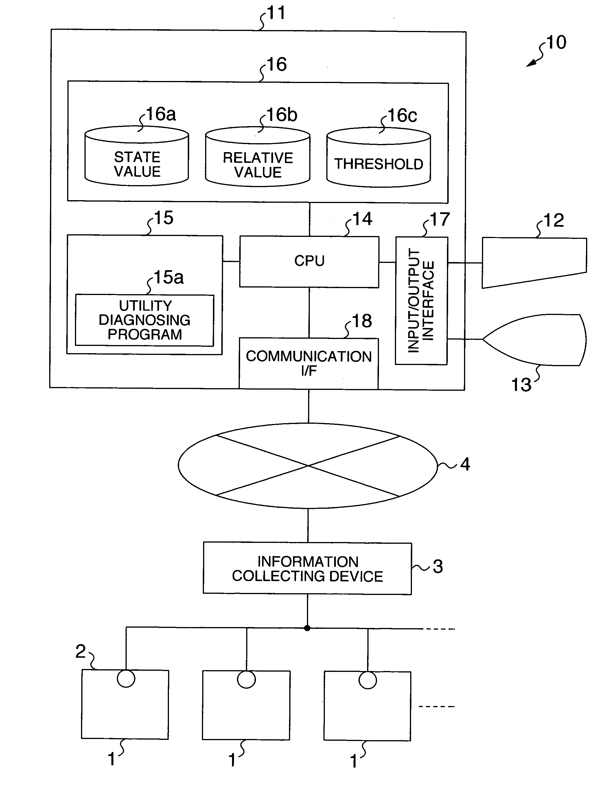
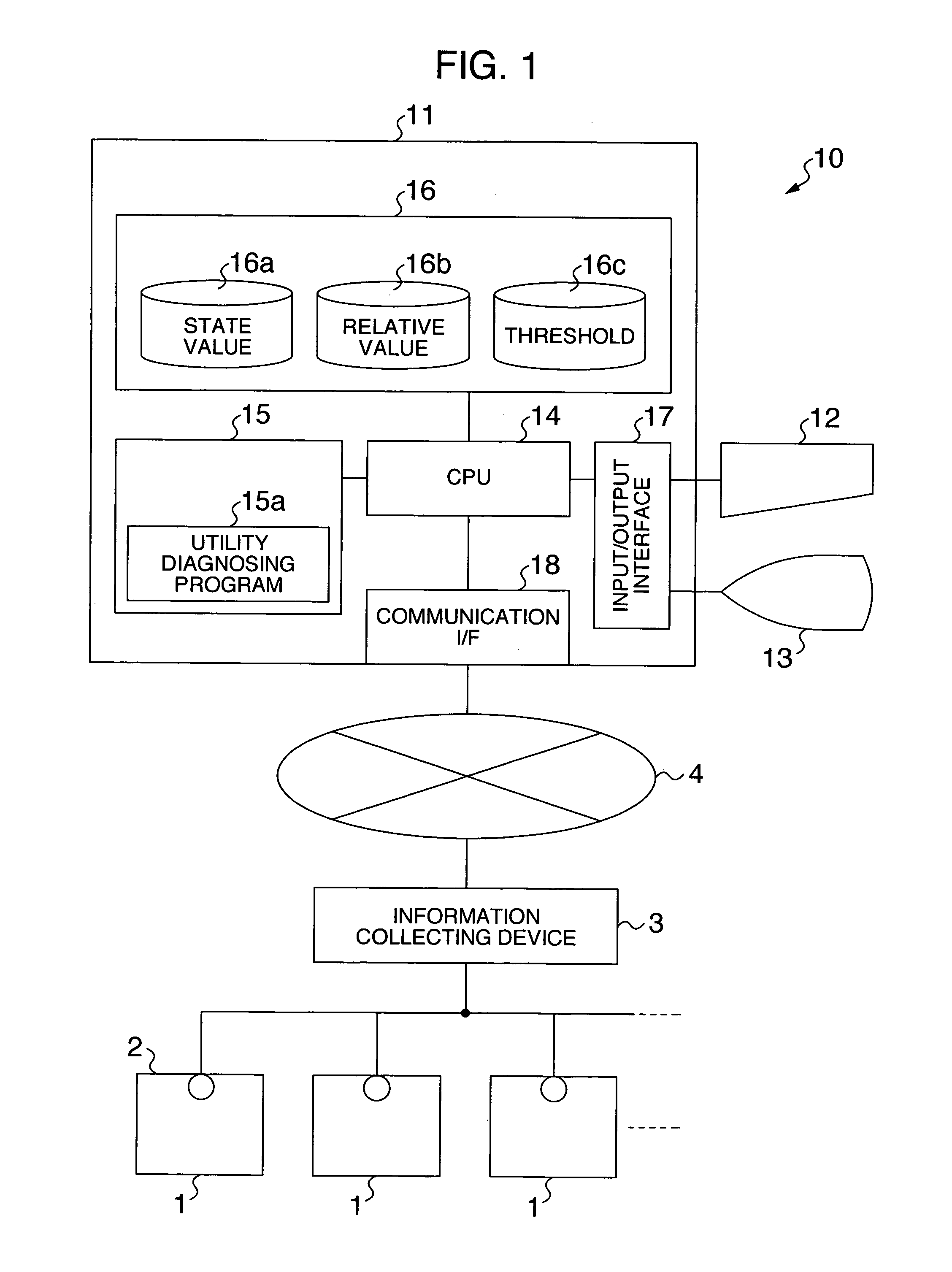
[0053] As shown in FIG. 1, the utility diagnosing system of the present embodiment diagnoses a plurality of utilities 1 of an identical type. The system comprises an information collecting device 3 for collecting state values from the utilities 1, and a utility diagnosing device 10 connected to the information collecting device 3 via a network 4. The utilities 1 to be diagnosed by the utility diagnosing system are, for example, air conditioners or the like provided in a building or the like. Each utility 1 is provided with sensors 2 for detecting a temperature, a current value, a voltage value, etc. indicative of its operating state. The information collecting device 3 collects state values from the sensors 2 of the utilities 1 and transmits them to the utility diagnosing device 10.

[0054] The utility diagnosing device 10 includes a co...


PUM


Abstract

A utility diagnosing equipment can recognize an abnormality or a normality in a plurality of utilities of an identical type, which would not be recognized when an absolute threshold is set. The equipment accepts state values from the plurality of utilities, sets an average value of the state values of each utility to a proxy value, finds a relative value between the state value of each utility and the proxy value thereof, and displays the relative value for each utility. The relative values of the utilities exceeding a predetermined threshold is highlighted.

Description

BACKGROUND OF THE INVENTION [0001] The present invention relates to utility diagnosing equipment for diagnosing a plurality of utilities of an identical type on the basis of state values from the plurality of utilities, and also relates to an operational program for the equipment and a utility diagnosing method. [0002] A utility such as an air conditioner is used, in many cases, together with a controller for controlling the utility. The controller has both a function of transmitting user's control instruction to the utility and a function of monitoring the state of the utility. Thus, when an abnormality takes place in the utility, the controller informs the user of the abnormality. [0003] As disclosed in JP-B-3119046 in these years, there is proposed a method for increasing a maintenance efficiency by monitoring such a utility as mentioned above from a remote place using a typical network technique. In this method, a controller monitors the state value of the installed utility. And...

Claims


Application Information

Patent Timeline
IPC IPC(8): G06F11/30F24F11/02G05B23/02G06Q50/00G06Q50/10G08B21/18G08B25/00G08B25/04H04Q9/00
CPCG05B23/0235F24F11/0086G05B2219/2638F24F11/30F24F11/63F24F11/38
Inventor SUZUKI, HIDEAKISAITO, MASAHIKOYOKOTA, TOSHIMITAIRA, TOMOTSUNE
Owner HITACHI LTD
Why Eureka
Try Eureka