Speed sensor fitting structure

Inactive Publication Date: 2006-09-14
HONDA MOTOR CO LTD
View PDF9 Cites 18 Cited by
  • Summary
  • Abstract
  • Description
  • Claims
  • Application Information

AI Technical Summary

Benefits of technology

[0011] According to an embodiment of the present invention, there is provided a portion where the sensor cover, vehicle sensor and sensor stay are fastened together by a common fastening bolt. Therefore, when the sensor cover is removed, the vehicle sensor is removed together,

Problems solved by technology

The removal of the brake caliper

Method used


Image

  • Speed sensor fitting structure
  • Speed sensor fitting structure
  • Speed sensor fitting structure

Examples


Example

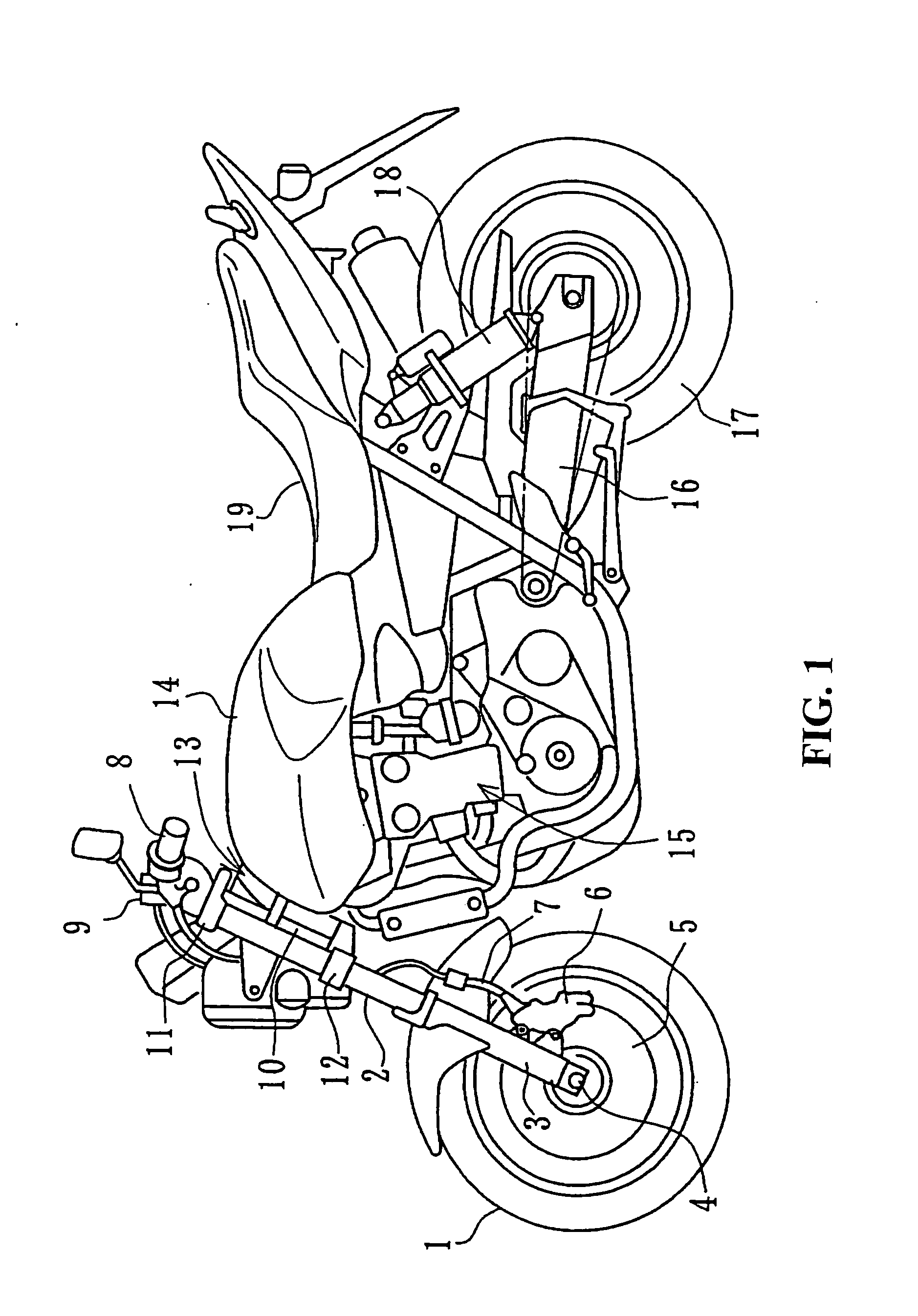
[0023] The following is a description of a preferred embodiment based on the drawings. FIG. 1 is a side view of a motorcycle according to an embodiment of the invention. A front wheel 1 is supported by a vehicle axis 4 at a lower end of a bottom case 3 at a lower end of a pair of left and right front forks 2.

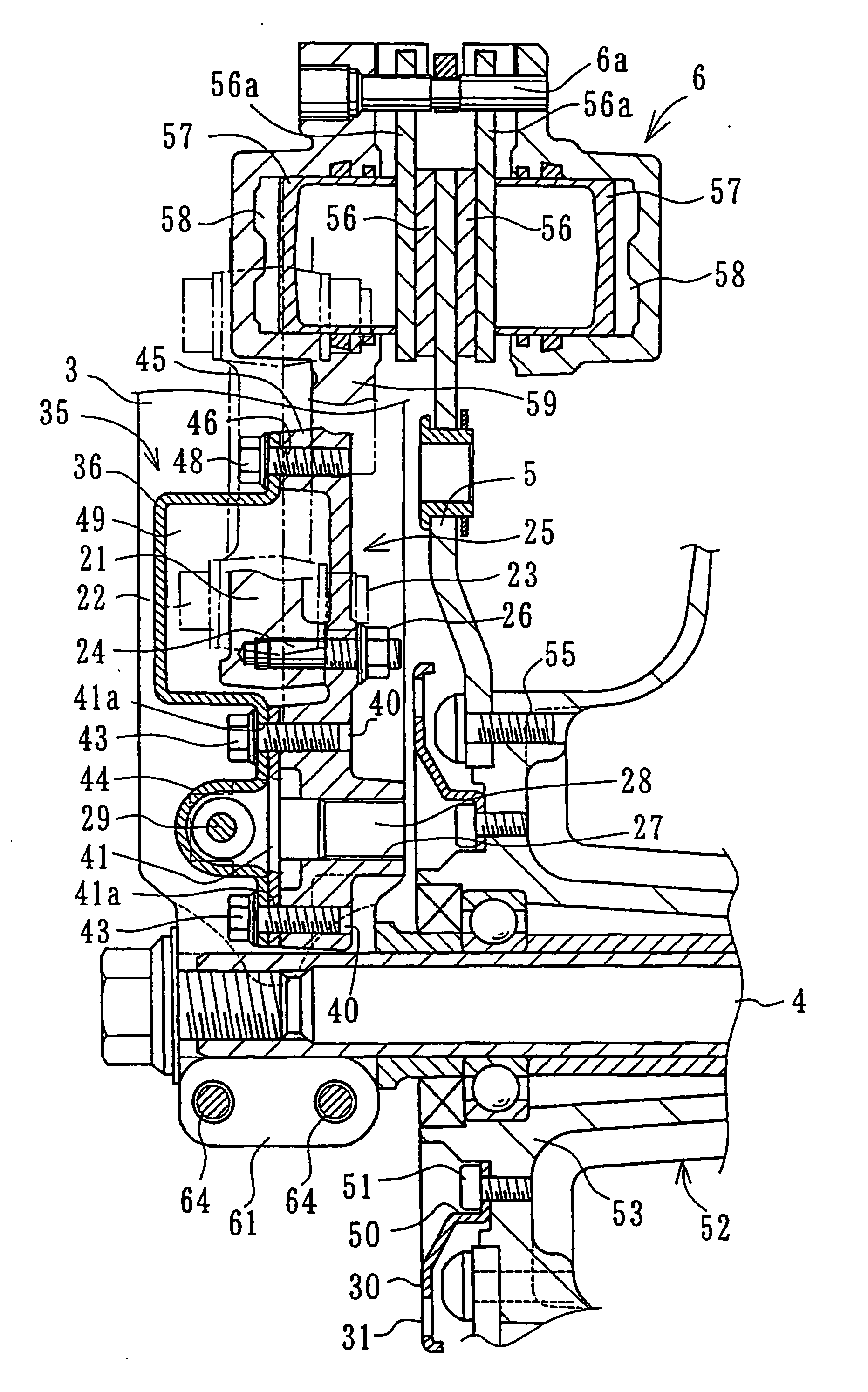
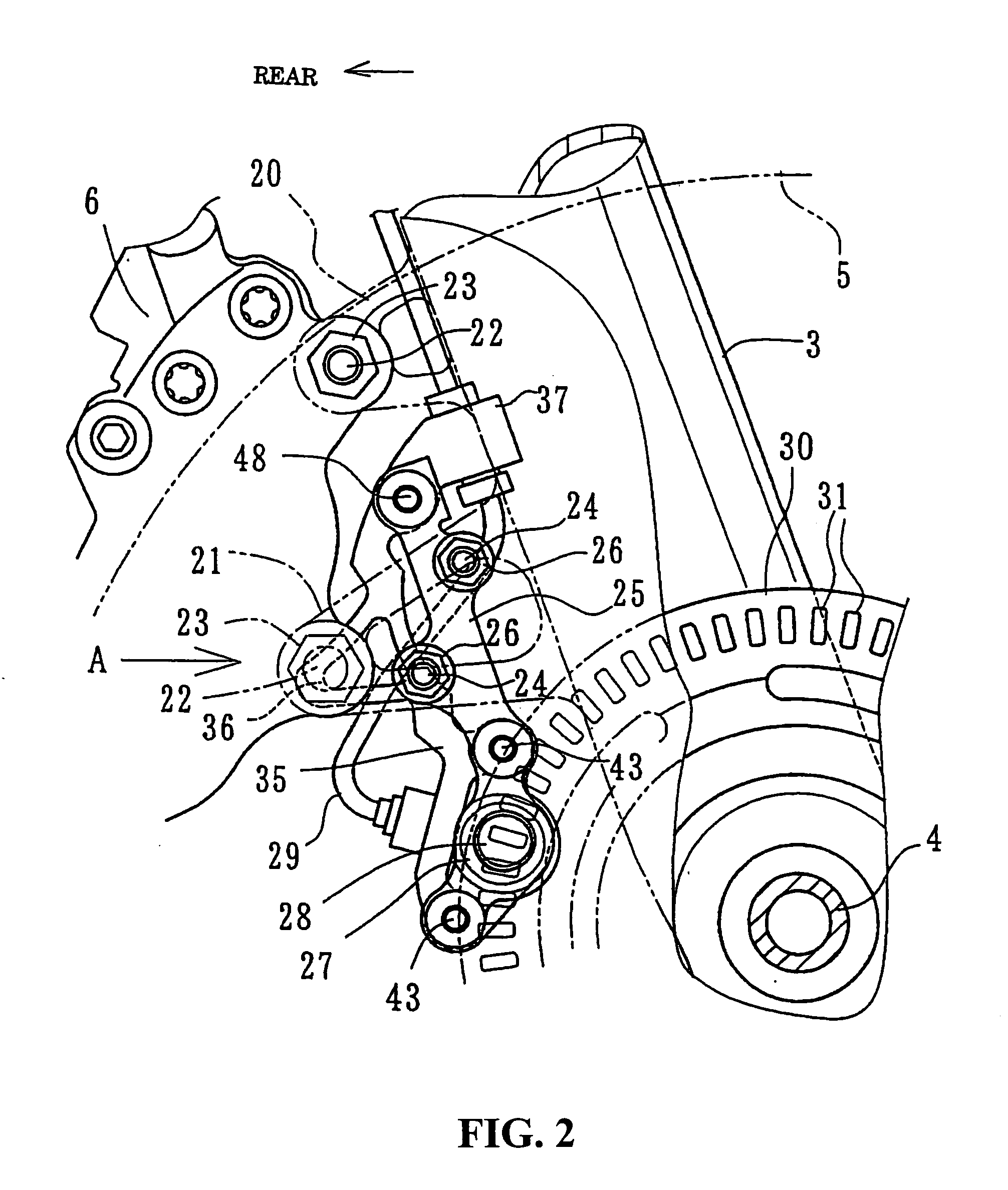
[0024] A brake disc 5 is provided on the same axis as the vehicle axis 4 at the front wheel 1 and a brake caliper 6 for making sliding contact with the brake disc 5 is directly fitted to a side surface at a rear end of the bottom case 3. A hydraulic cable 7 extends upwards along the front forks 2 from the brake caliper 6 and passes through a master cylinder 9 provided in the vicinity of a handlebar grip 8.

[0025] The upper section of the front fork 2 is supported in a freely rotating manner with respect to a head pipe 10 via a top bridge 11 and bottom bridge 12. The head pipe 10 is provided at a front end of a vehicle frame 13. A fuel tank 14 is disposed adjacent to a liquid-co...


PUM


Abstract

When a vehicle speed sensor is provided as a separate unit, the vehicle sensor should be removed when a vehicle wheel is changed. A brake caliper is fitted to an upper stay and a lower stay formed at a lower part of the front fork supporting the front wheel. The sensor stay is fitted to the inside of the lower stay in the vicinity of the brake caliper. A sensor cover is fastened integrally in an overlapping manner to the outside of the sensor stay. A projection formed on the sensor cover overlaps with a fitting bolt of the brake caliper. Thus, it is not possible to remove the brake caliper without first removing the sensor cover. Further, a vehicle speed sensor is sandwiched by the sensor stay and the lower end of the sensor cover and the three members are fastened together.

Description

CROSS-REFERENCE TO RELATED APPLICATIONS [0001] The present application claims priority under 35 USC 119 to Japanese Patent Application No. 2005-064878 filed on Mar. 9, 2005 the entire contents of which are hereby incorporated by reference. FIELD OF THE INVENTION [0002] The present invention relates to a structure for fitting a vehicle speed sensor to a front fork of a motorcycle. DESCRIPTION OF BACKGROUND ART [0003] Vehicle sensors for detecting pulses of a pulser ring that are rotating integrally with a front wheel by using magnetic change in a non-contact manner are well-known. In the event that this vehicle speed sensor is provided for a motorcycle of the type where a brake caliper is fitted to a front fork via a carry bracket, it is possible to fit the vehicle speed sensor to the carry bracket. On the other hand, with motorcycles where a brake caliper is fitted directly to a front fork without using a caliper bracket, the vehicle speed sensor is fitted directly to the front fork...

Claims


Application Information

Patent Timeline
IPC IPC(8): B62L5/00B62J99/00
CPCB60T8/1706B60T8/171B62J99/00B62J2099/002B62K25/08B62K2207/00G01P1/026B62J45/423B62J45/412
Inventor NIMURA, TAISUKEASHIGAI, TAKASHIIWAI, TOSHIYUKI
Owner HONDA MOTOR CO LTD
Why Eureka
Try Eureka