Lamp unit of vehicle headlamp

a technology of headlamps and lamps, which is applied in the direction of fixed installation, lighting and heating apparatus, lighting support devices, etc., can solve the problems of poor long-distance visibility and non-enhancing the luminosity of the region, and achieve excellent long-distance visibility

Inactive Publication Date: 2007-04-19
KOITO MFG CO LTD
View PDF4 Cites 125 Cited by
  • Summary
  • Abstract
  • Description
  • Claims
  • Application Information

AI Technical Summary

Benefits of technology

[0012] One or more embodiments of the present invention provide a projector-type lamp unit of a vehicle headlamp that uses a light-emitting element as a light source in which the lamp unit is provided with first and second light source units ar

Problems solved by technology

This does not enhance the luminosity of the region near the cutoff line in the high beam light distribution pa

Method used


Image

  • Lamp unit of vehicle headlamp
  • Lamp unit of vehicle headlamp
  • Lamp unit of vehicle headlamp

Examples


Embodiment Construction

[0038] Exemplary embodiments of the invention will be described with reference to the accompanying drawings.

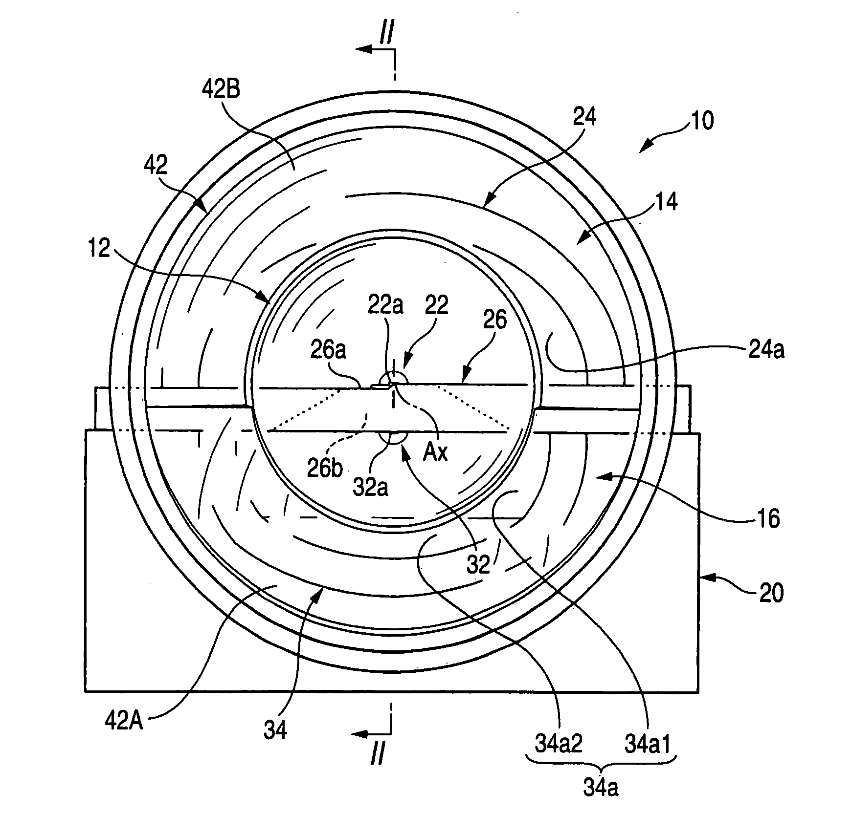
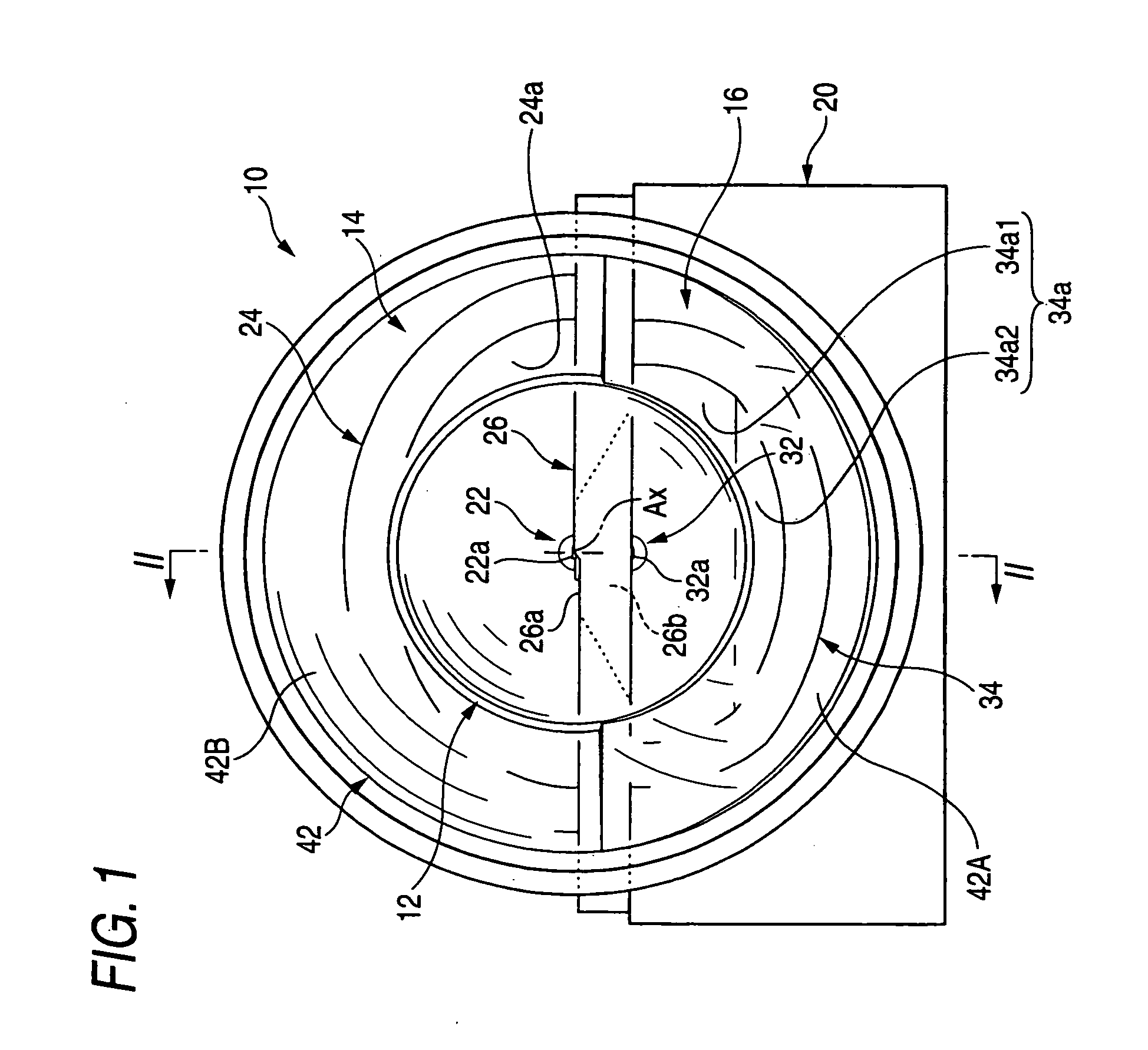
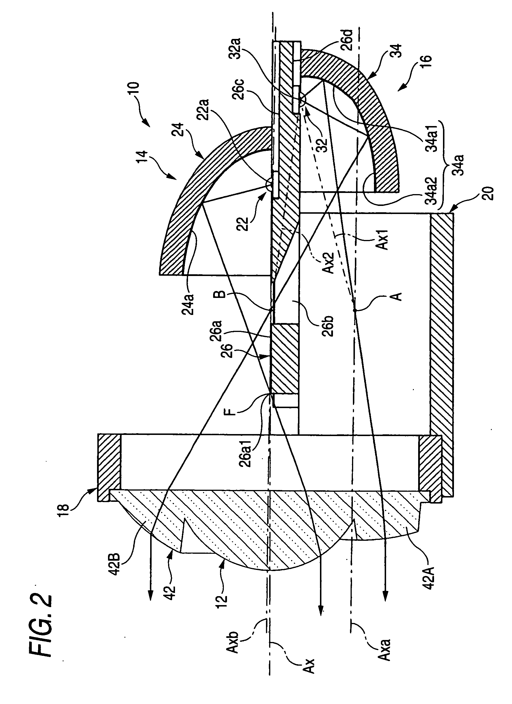
[0039]FIG. 1 is a front view of a lamp unit 10 according to an exemplary embodiment of the invention. FIG. 2 is a cross-sectional view taken along the line II-II in FIG. 1. FIG. 3 is a drawing similar to FIG. 2 showing the optical path in the lamp unit 10 in details.

[0040] As shown in the figures, the lamp unit 10 according to the exemplary embodiment is a lamp unit that is used while incorporated into a vehicle headlamp as part thereof. The lamp unit 10 is provided with a projection lens 12 arranged on an optical axis Ax extending in a front / rear direction of a vehicle, a first light source unit 14 and a second light source unit 16 arranged behind the projection lens 12, and an additional projection lens 42. The lamp unit 10 is arranged so that its optical axis Ax will extend in a direction 0.5 to 0.6 degrees downward with respect to the front / rear direction of a vehicle wh...


PUM


Abstract

A low beam light distribution pattern is formed by turning on a first light source unit and a high beam light distribution pattern is formed by additionally turning on a second light source unit. The second reflector of the second light source unit has reflecting faces of vertical cross-sectional shapes formed by two types of ellipses whose first focal point is on a center of emission of a second light-emitting element and whose second focal points are respectively positioned on points A, B. The additional lens whose rear focal points are on the second focal points A, B is arranged on a circumference of a projection lens. When the second light source unit is turned on, a high beam additional light distribution pattern is formed that vertically strides over the cutoff line of the low beam light distribution pattern.

Description

[0001] This application claims foreign priority from Japanese Patent Application No. 2005-298414, filed on Oct. 13, 2005, the entire contents of which are hereby incorporated by reference. BACKGROUND OF THE INVENTION [0002] 1. Field of the Invention [0003] The present invention relates to a lamp unit of a vehicle headlamp, and in particular to a projector-type lamp unit that uses a light-emitting element such as a light-emitting diode as a light source. [0004] 2. Related Art [0005] Recently, in vehicle headlamps, light-emitting elements such as light-emitting diodes become to be used as light sources. [0006] For example, disclosed in JP-A-2003-317513 is a so-called projector-type lamp unit provided with a projection lens arranged on an optical axis extending in a front / rear direction of a vehicle, a light-emitting element arranged upward behind a rear focal point of the projection lens and in proximity to the optical axis, and a reflector for reflecting light from the light-emitting...

Claims


Application Information

Patent Timeline
IPC IPC(8): F21V7/00
CPCF21S48/1159F21S48/1163F21S48/1258F21S48/1275F21S48/1358F21S48/1388F21S48/1747F21Y2101/02F21Y2115/10F21S41/148F21S41/255F21S41/265F21S41/321F21S41/323F21S41/338F21S41/365F21S41/60F21S41/663F21S41/155F21S41/334
Inventor TSUKAMOTO, MICHIONAGANAWA, MASAHITO
Owner KOITO MFG CO LTD
Why Eureka
Try Eureka