Socket assembly

Inactive Publication Date: 2007-07-26
HON HAI PRECISION IND CO LTD
View PDF5 Cites 22 Cited by
  • Summary
  • Abstract
  • Description
  • Claims
  • Application Information

AI Technical Summary

Benefits of technology

[0007]Accordingly, an object of the present invention is to provide an LGA connector that can prevent undesired engag

Problems solved by technology

In this case, the solder balls 51′ of the terminals 5′ can not be accurately soldered with the printed circuit

Method used


Image

  • Socket assembly
  • Socket assembly
  • Socket assembly

Examples


Example

[0019]Reference will now be made to the drawings to describe the present invention in detail.

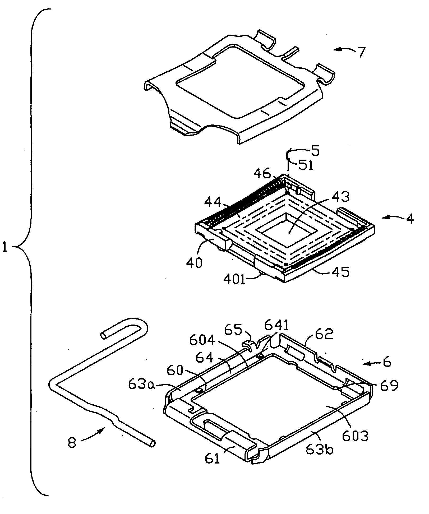
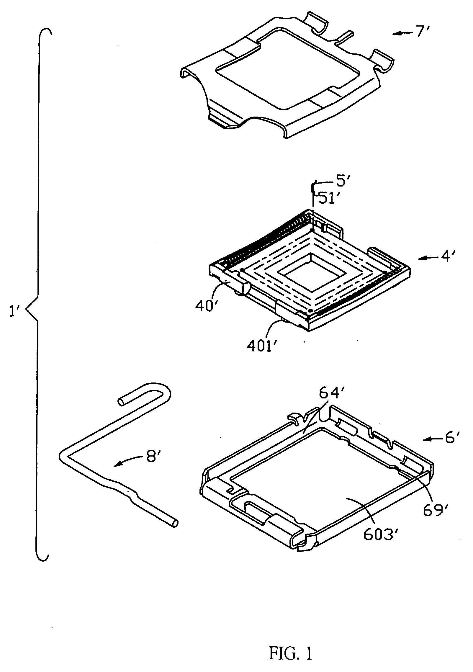
[0020]Referring to FIGS. 4-8, an electrical socket assembly 1 in accordance with the embodiment of the present invention comprises an insulative housing 4, a plurality of terminals 5 received in the housing 4, a stiffener 6 defined around the housing 4, a metal clip 7 pivotably engaged on one end of the stiffener 6, and a lever 8 engaged on an opposite end of the stiffener 6 for fastening the clip 7 onto the housing 4. A chip module is ready to be disposed between the housing 4 and the clip 7, for connecting with the printed circuit board via the connector 1.

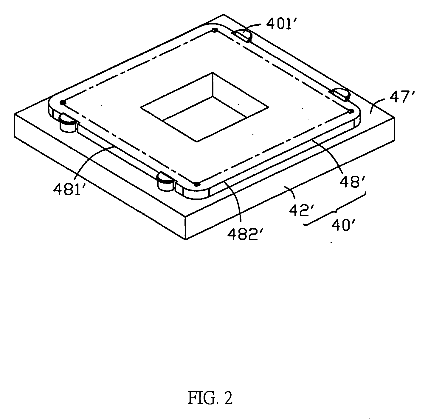
[0021]The housing 4 has a substantially rectangular configuration with a plurality of side surfaces 40 and a center concave 43 thereof. A plurality of passageways 46 is defined in the housing 4 for receiving a corresponding number of electrical contacts 5 therein. In addition, the housing 4 comprises an upper surface 44 and a lower surfa...


PUM


Abstract

An electrical connector (1) comprises an insulative housing (4), a stiffener (6) defined around the housing (4), a clip (7) pivotably engaged on one end of the stiffener (6), and a lever (8) engaged on an opposite end of the stiffener (6) for fastening the clip (7) onto the housing (4). The housing (4) comprises an upper surface (44) and a lower surface (45) opposite to the upper surface (44) and a platform surface (47) projected between the upper surface (44) and the lower surface (45) and a planar sidewall (40) surrounded thereof. The sidewall (1) comprises an upper section (42) and a lower section (48) that is the circumference of the upper sidewall (42) is longer than that of the lower sidewall (48). The lower sidewall (48) is enveloped by the first sidewall (481) and the second sidewall (482) opposite to the first sidewall (481) and configured as a shape similar to that of the opening (603) of the stiffener (6), hence the housing (4) can be interferentially mounted into the opening (603) of the stiffener (6). The housing (4) defines a number of positioning poles (401) on the platform surface (47) adjacent to the outside of the first sidewall (481) of the housing (4). The stiffener (6) defines a number of recesses (69) for receiving the poles (401). In addition, the stiffener (6) defines a number of projections (641) projected toward the platform surface (47) of the housing (4) for engaging with the platform surface (1).

Description

BACKGROUND OF THE INVENTION[0001]1. Field of the Invention[0002]The present invention relates to an electrical socket assembly for electrically connecting an electronic package such as an chip module with a circuit substrate such as a printed circuit board (PCB), and particularly to an electrical socket assembly adapted for receiving a chip module therein and electrically connecting with a PCB.[0003]2. Description of the Prior Art[0004]Referring to FIGS. 1-3, a convention electrical connector 1′ is illustrated. The connector 1′ comprises an insulative housing 4′, a stiffener 6′ defined around the housing 4′, a metal clip 7′ pivotably engaged on one end of the stiffener 6′, and a lever 8′ engaged on an opposite end of the stiffener 6′ for fastening the clip 7′ onto the housing 4′. The housing 4′ comprises an upper surface 44′ and a lower surface 45′ opposite to the upper surface 44′ and a platform surface 47′ projected between the upper surface 44′ and the lower surface 45′ and a pla...

Claims


Application Information

Patent Timeline
IPC IPC(8): H01R12/00
CPCH01R12/88H05K7/1053
Inventor YU, WEIMA, HAO-YUN
Owner HON HAI PRECISION IND CO LTD
Why Eureka
Try Eureka