Flexible connector for implantable wiring harness

a flexible connector and wiring harness technology, applied in the direction of coupling devices, electrical equipment, coupling devices, etc., can solve the problems of serious obstacles to reliability and implantability, increase the number of separate power and control channels required in the wiring harness, and challenge the ability of the medical industry to develop, test and commercialize suitable products, etc., to achieve the effect of reducing strain and maximizing patient quality of li

Active Publication Date: 2008-01-10
PMI IND INC
View PDF12 Cites 55 Cited by
  • Summary
  • Abstract
  • Description
  • Claims
  • Application Information

AI Technical Summary

Benefits of technology

[0010] The elongated plug connector includes a bore for receiving a first set of power and sensor cables. A plurality of spaced apart first electrical contacts are received in the bore, wherein the first set of power and sensor cables are electrically connected to the plurality of first electrical contacts. A plurality of second electrical contacts in the receptacle connector are received electrically connected to the plurality of first contacts upon assembly of the plug connector to the receptacle connector. A second set of power and sensor cables are electrically connected to the plurality of second electrical contacts. The second set o

Problems solved by technology

The need for implantable mechanical assist or replacement organs and devices is growing at a fast pace that challenges the ability of the medical industry to develop, test, and commercialize suitable products.
While innovative advances in materials, electronics, and technology propel this industry forward, the reliance on conventional approaches to the implantable wiring harnesses that connect these many devices together presents serious obstacles to reliability and implant

Method used


Image

  • Flexible connector for implantable wiring harness
  • Flexible connector for implantable wiring harness
  • Flexible connector for implantable wiring harness

Examples


first embodiment

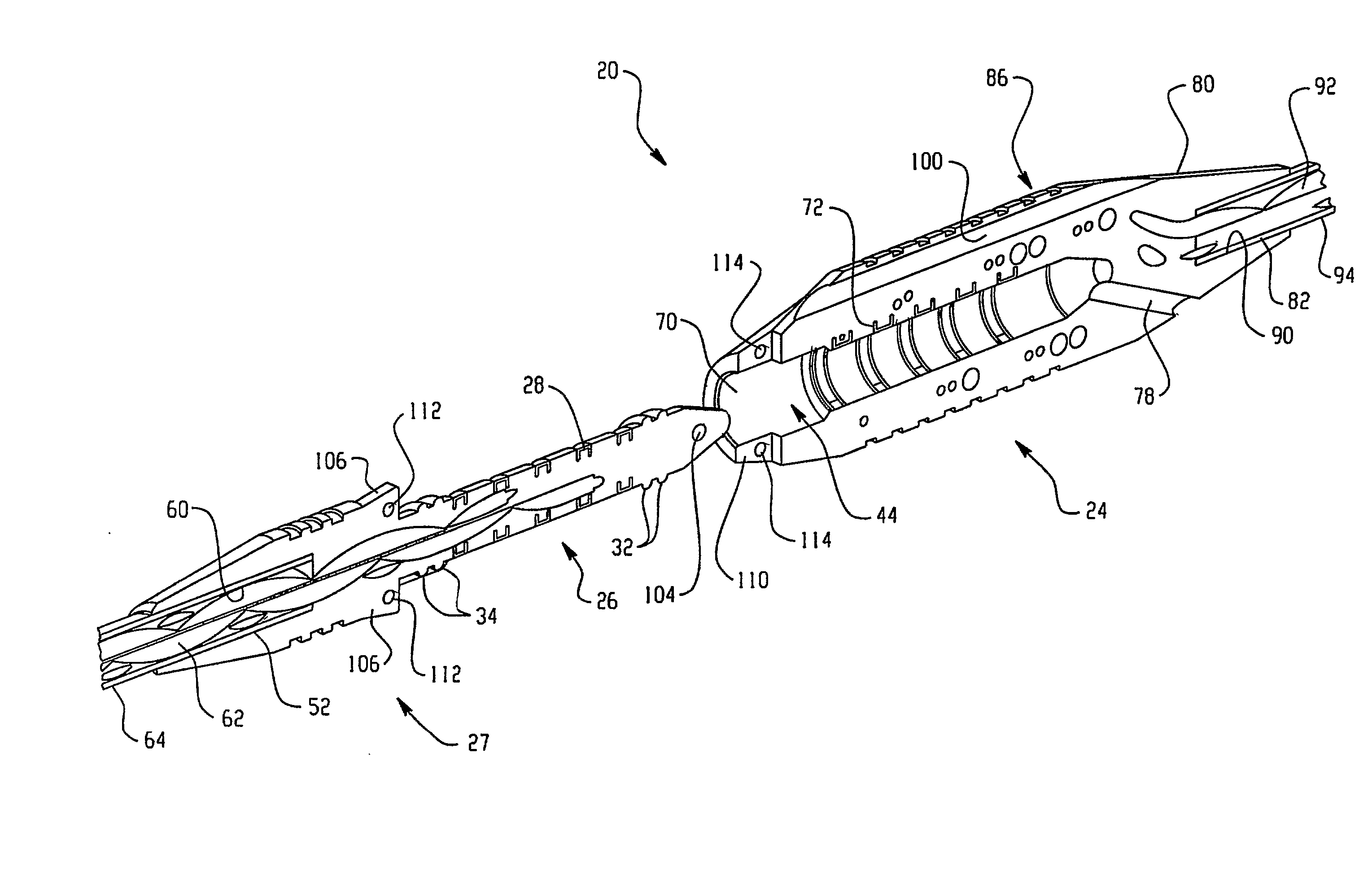
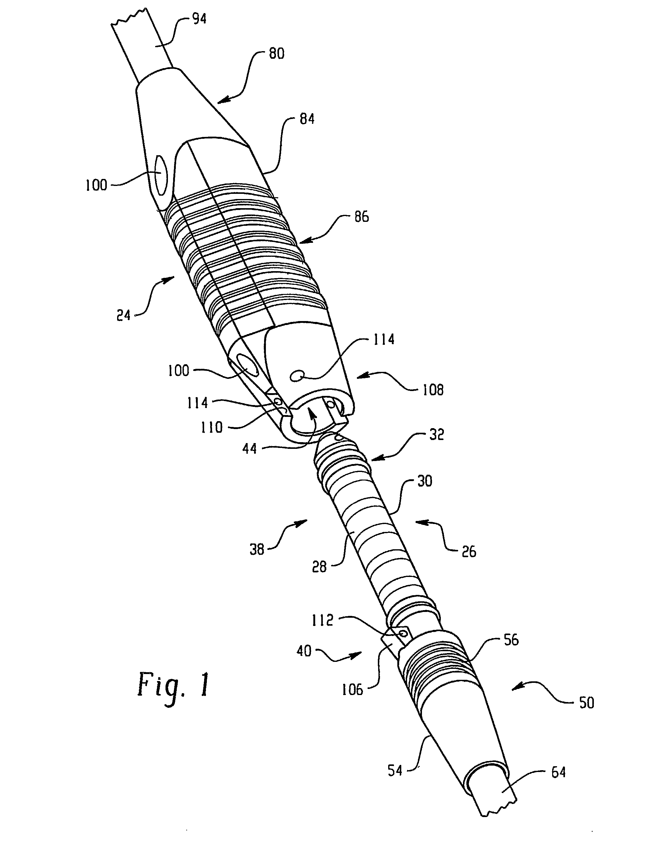
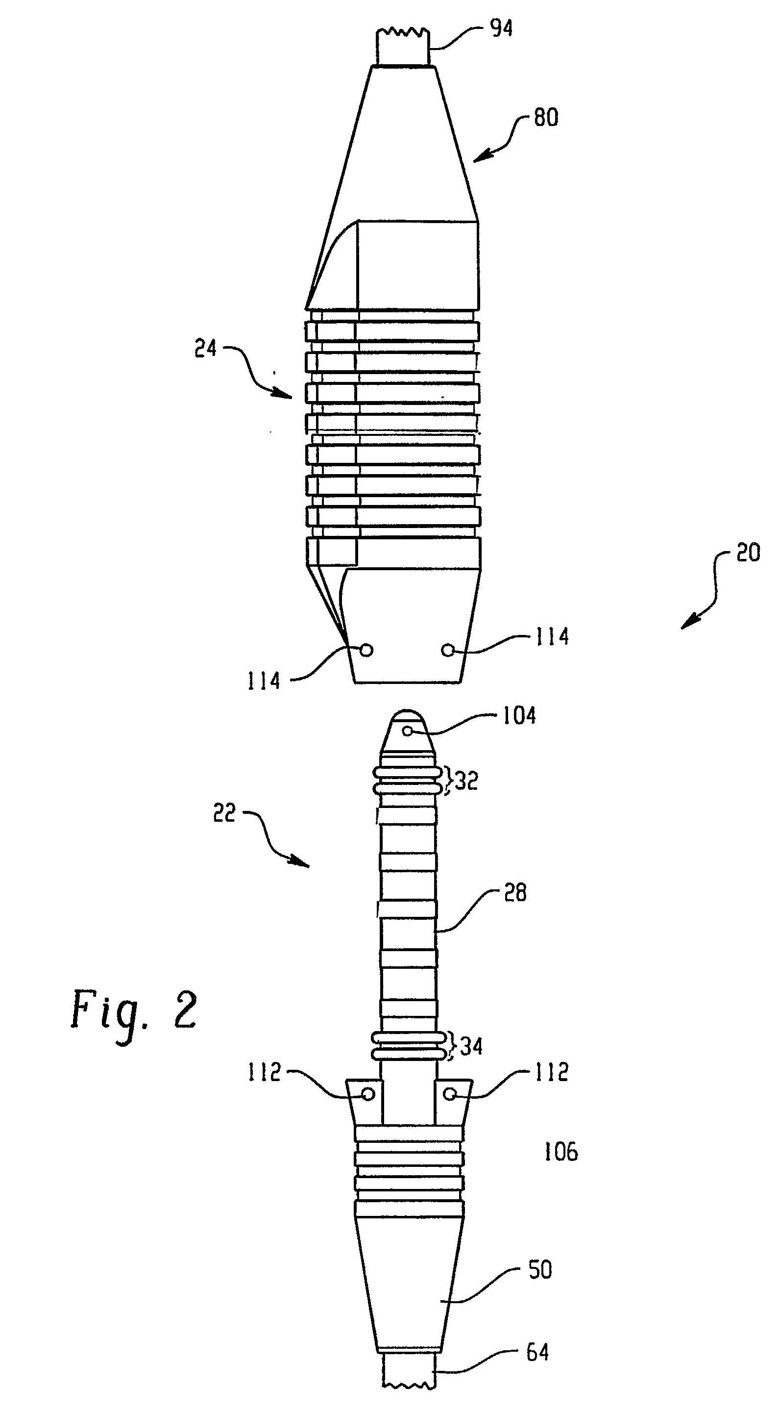
[0029] It should, of course, be understood that the description and drawings herein are merely illustrative and that various modifications and changes can be made in the structures disclosed without departing from the spirit of the invention. Like numerals refer to like parts throughout the several views. With reference to FIGS. 1 and 2, a generally linear flexible connector assembly 20 in accordance with the present invention comprises a plug connector 22 and a receptacle connector 24. Both the plug connector and receptacle connector are formed at least partially from a flexible elastomeric material, preferably a medical grade elastomeric material.

[0030] The plug connector 22 includes an elongated member 26 and at least one electrical contact. In this embodiment, the plug connector includes five longitudinally spaced apart electrical contacts 28 disposed about a portion of the elongated member; however, it should be appreciated that the plug connector 22 can include more or less th...

second embodiment

[0041] Similar to the aforementioned embodiment, a second embodiment is shown in FIGS. 7-13 Since most of the structure and function is substantially identical, reference numerals with a single primed suffix (′) refer to like components (e.g., plug connector is referred to by reference numeral 22′), and new numerals identify new components in the additional embodiment of FIGS. 7-10.

[0042] With reference to FIG. 7, a typical wiring harness 150 includes a hard-wired battery 152, an electronic control unit 154 with a multiple bulkhead, and an actuator 156 with a bulkhead. A first cable or cord 158 interconnects the battery and the electronic control unit and a second cable or cord 160 interconnects the actuator and the electronic control unit. A connector assembly 20′ separates the second cable into first and second sections 162 and 164, respectively.

[0043] As shown in FIGS. 8-10, the connector assembly 20′ includes a plug connector 22′ and a receptacle connector 24′. Similar to the f...


PUM


Abstract

The present invention is directed to a linear connector assembly comprising a plug connector (22) and a receptacle connector (24). The plug connector (22) includes an elongated member (26), and an electrical contact (72) disposed about a portion of the elongated member. The receptacle connector (24) includes a wall defining a cavity (44) dimensioned to sealingly receive the elongated member, and an electrical contact having a surface disposed in the wall for electrical connection with the plug contact. The electrical contacts of the plug connector (22) and the receptacle connector (24) have spherical surface portions whereby a spherical interlace between the electrical contacts is formed upon make-up and reduces voltage drops between the contacts.

Description

BACKGROUND OF THE INVENTION [0001] The present disclosure relates to a connector assembly and more particularly to a flexible connector assembly for an implantable wiring harness. However, it is to be appreciated that the present invention is also amenable to other like environments and applications. [0002] The need for implantable mechanical assist or replacement organs and devices is growing at a fast pace that challenges the ability of the medical industry to develop, test, and commercialize suitable products. While innovative advances in materials, electronics, and technology propel this industry forward, the reliance on conventional approaches to the implantable wiring harnesses that connect these many devices together presents serious obstacles to reliability and implantability. [0003] Implanted wiring harnesses are subjected to a spectrum of forces and environmental stresses that must be withstood throughout the lifetime of the device. [0004] Moreover, as the sophistication a...

Claims


Application Information

Patent Timeline
IPC IPC(8): H01R24/04H01R24/58
CPCH01R13/2478H01R13/5221H01R13/5224H01R13/5227H01R13/5845H01R2201/12H01R13/639H01R24/58H01R35/00H01R2107/00H01R13/631
Inventor MARINO, JAY
Owner PMI IND INC
Why Eureka
Try Eureka