Connector holder unit, carriage, recording apparatus, and liquid ejecting apparatus

a technology of connector holder and carriage, which is applied in the direction of coupling device connection, coupling parts engagement/disengagement, printing, etc., can solve the problems of deformation of the connector holder unit, the inability to attach the carriage to the deformed connector holder unit, and the deterioration of signal transmission

Inactive Publication Date: 2008-03-20
SEIKO EPSON CORP
View PDF3 Cites 9 Cited by
  • Summary
  • Abstract
  • Description
  • Claims
  • Application Information

AI Technical Summary

Benefits of technology

[0009] An advantage of some aspects of the invention is that it provides a connector holder unit in which a circuit substrate and a connector can be installed to a connector holder in an easy manner and which does not generate foreign bodies at a time when the circuit substrate and the connector are installed, a carriage having the connector holder unit, and a recording apparatus and a liquid ejecting apparatus that have the carriage.
[0011] In the first aspect, since the connector holder unit is formed separately from the carriage, it is not needed to install the connector and the circuit substrate to the connector holder by using a sliding method, and accordingly, a problem such as generation of foreign bodies due to cut of resists do not occur. In addition, an operation for installment of the connector and the circuit substrate 9 can be simplified, compared to a case where the connector and the circuit substrate are installed after attachment of the connector holder to the carriage.
[0014] In the second aspect, since the circuit substrate is attached in a status that the circuit substrate is slightly movable in the front or of rear direction of the connector holder, a spring force of the contact of the connector reduces a biasing force applied to the connector holder through the circuit substrate, and whereby bending deformation of the connector holder can be prevented.
[0016] In the third aspect, since there is used a configuration in which the circuit substrate is attached to the connector holder by a pivoting movement without being sled into the connector holder, a problem such as cut of the resists due to a mistake in the attachment of the circuit substrate does not occur. In addition, since elastic deformation of the circuit substrate during the attachment operation does not occur, deterioration of quality of the circuit substrate can be prevented.
[0018] In the fourth aspect, a carriage that can prevent generation of foreign bodies such as small fragments cut away from the resists and assuredly transmit information on the ink cartridge to the circuit substrate side is provided.

Problems solved by technology

Thus, there is a possibility that foreign bodies such as cut resists are interposed between the contact portions to cause deterioration of signal transmission therebetween.
In addition, since the connector holder is provided inside the carriage in advance and the circuit substrate and the connector are required to be installed to the connector holder thereafter, it is relatively difficult to install the circuit substrate and the connector.
Thus, there is a case where the deformed connector holder unit cannot be attached to the carriage.

Method used


Image

  • Connector holder unit, carriage, recording apparatus, and liquid ejecting apparatus
  • Connector holder unit, carriage, recording apparatus, and liquid ejecting apparatus
  • Connector holder unit, carriage, recording apparatus, and liquid ejecting apparatus

Examples


Embodiment Construction

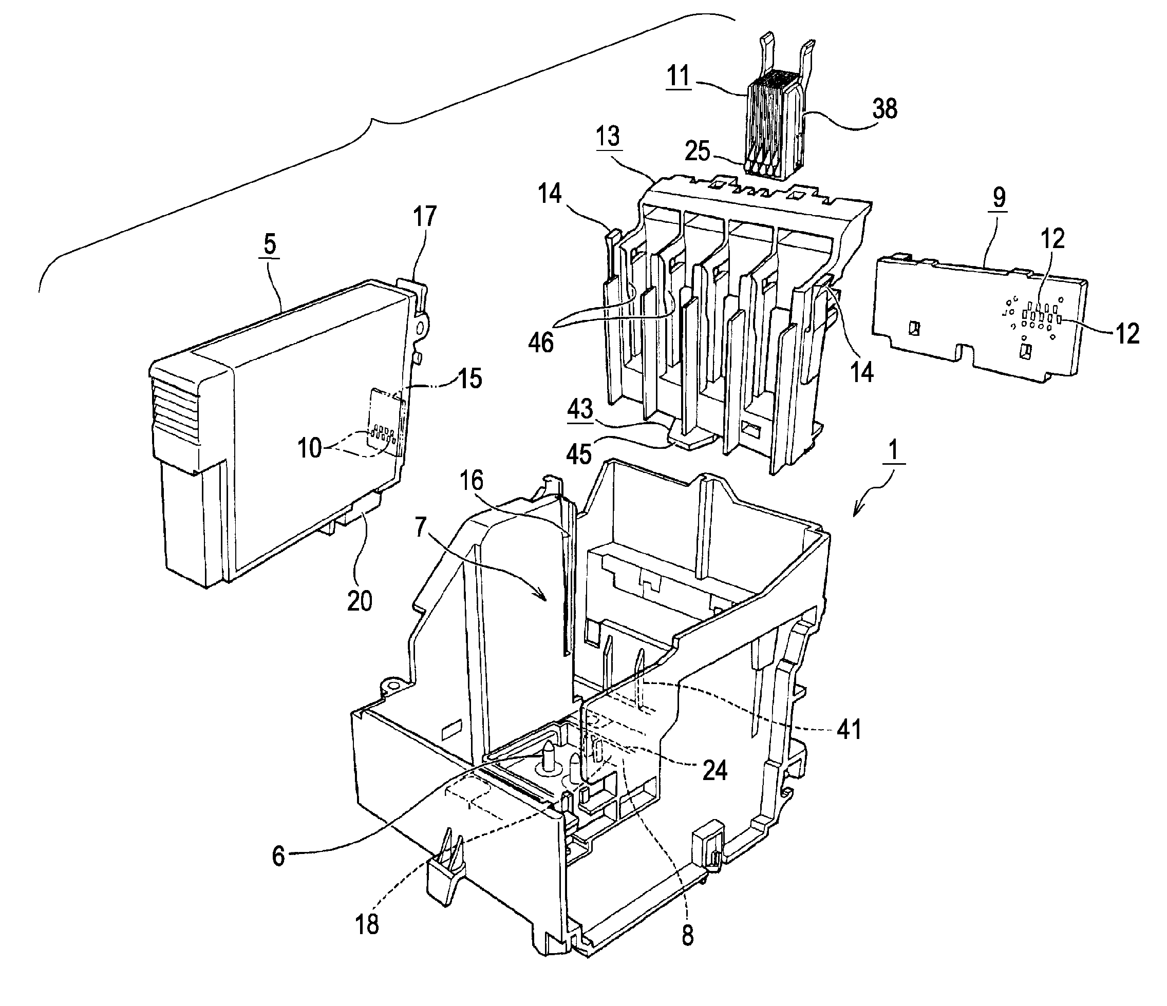
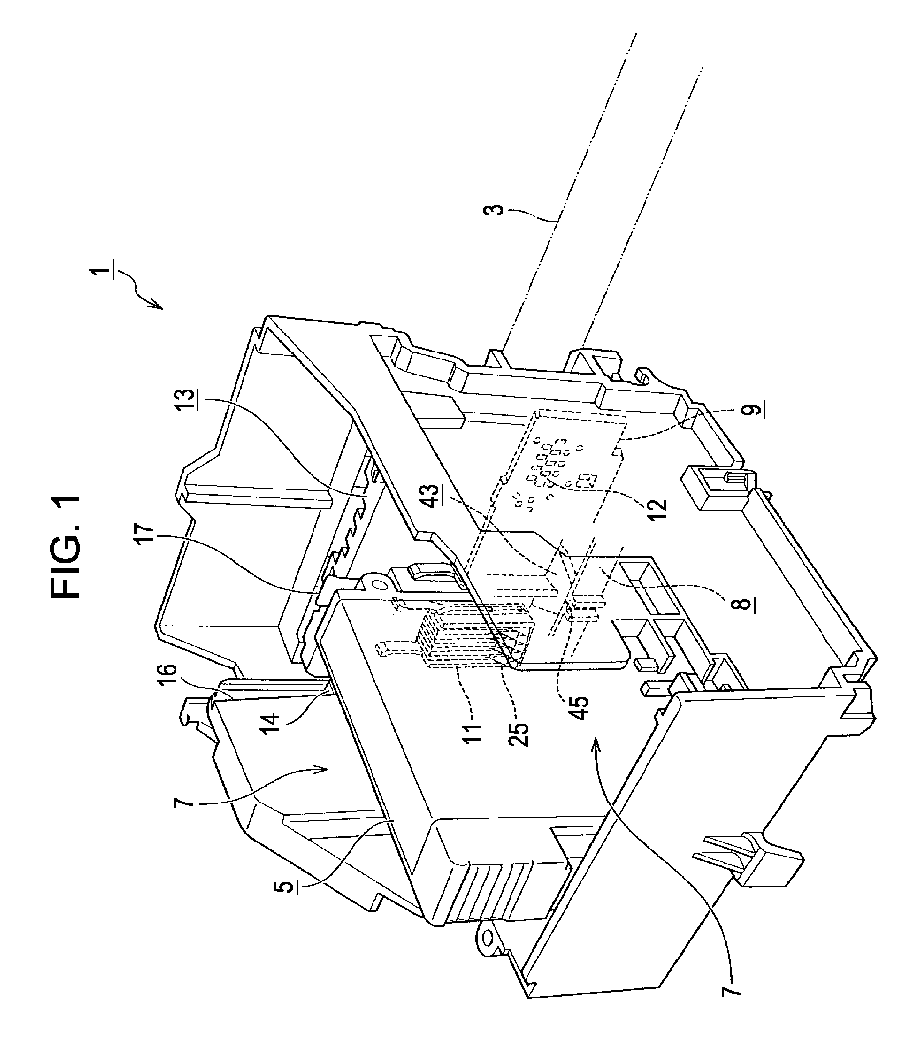
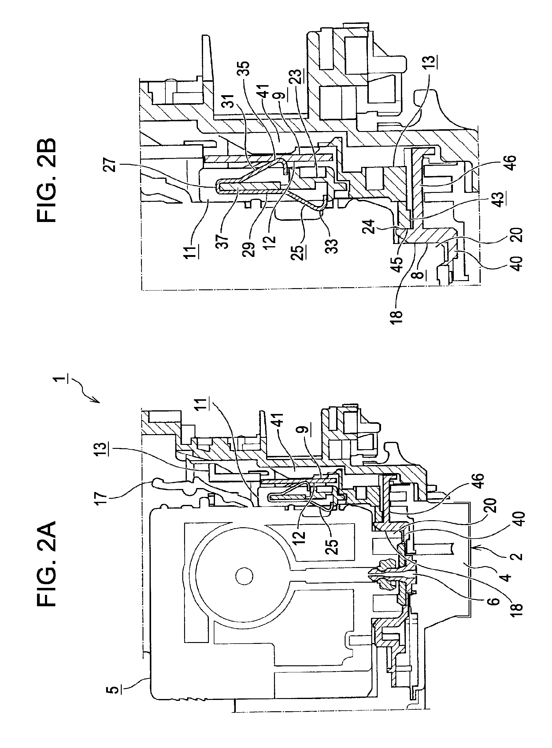
[0035] Hereinafter, an embodiment of the present invention will be described with reference to the accompanying drawings. FIG. 1 is a perspective view of a carriage for an ink jet printer according to an embodiment of the invention. FIG. 2A is a side sectional view of a connector and the vicinity thereof according to an embodiment of the invention. FIG. 2B is an enlarged side sectional view of the connector and a lower side thereof. FIG. 3 is a perspective view of the inside of a carriage according to an embodiment of the invention at a time right before installment of a connector holder unit. FIG. 4 is a perspective view of the inside of the carriage at a time when the connector holder unit is installed. FIG. 5 is an exploded perspective view of constituent members adjacent to the connector holder according to an embodiment of the invention. FIG. 6 is a longitudinal sectional view of a connector according to an embodiment of the invention. FIG. 7 is a perspective view of the inside...


PUM


Abstract

A connector holder unit that is formed separately from a carriage capable of housing an ink cartridge and can be attached to the inside of the carriage includes a connector holder, a connector having a plurality of contact arms that is installed to the connector holder, and a circuit substrate having a plurality of conductive connection portions that is installed to the connector holder, wherein contact terminals of the plurality of contact arms of the connector are configured to elastically contact the conductive connection portions of the circuit substrate and conductive connection portions of the ink cartridge so as to electrically conduct between the circuit substrate and the ink cartridge when the connector holder unit is attached to the carriage.

Description

BACKGROUND [0001] 1. Technical Field [0002] The present invention relates to a connector holder unit implementing electrical conduction between an ink cartridge that is housed in a carriage with a connector and a circuit substrate installed thereto and the circuit substrate for reading information on the ink cartridge housed in a carriage through the circuit substrate, a carriage having the connector holder unit, and a recording apparatus having the carriage. [0003] In addition, the invention relates to a liquid ejecting apparatus such as an ink jet recording apparatus performing recording (ejecting liquid) on a recording medium (liquid ejecting medium) by ejecting (injecting) liquid such as ink from its head. [0004] Here, the term “liquid ejecting apparatus” is used for referring not only to a recording apparatus, such as a printer, a copier, and a facsimile machine, having an ink jet recording head for ejecting ink from the recording head so as to perform recording on a recording ...

Claims


Application Information

Patent Timeline
Patent Type & Authority Applications(United States)
IPC IPC(8): H01R13/62
CPCB41J2/1752B41J2/17526H01R12/83H01R12/714H01R12/523
Inventor NAKANO, YOSUKESATO, TAKASHIFUKUMASU, KEIICHIRO
Owner SEIKO EPSON CORP
Why Eureka
Try Eureka