Lighting device

a technology of lighting device and light source, which is applied in the direction of lighting and heating apparatus, instruments, machines/engines, etc., can solve the problems of not being able to uniformly illuminate the parts of the lighting device, the parts to be irradiated, and the display designed parts or the display designed parts, etc., to achieve the effect of increasing the utility of the instrument devi

Inactive Publication Date: 2008-10-30
CALSONIC KANSEI CORP
View PDF10 Cites 7 Cited by
  • Summary
  • Abstract
  • Description
  • Claims
  • Application Information

AI Technical Summary

Benefits of technology

[0021]Therefore, the lighting device can increase the utility of the instrument device of the motor vehicle.

Problems solved by technology

The above conventional lighting device, however, encounters a problem in that the lighting device cannot uniformly illuminate all parts to be irradiated of the display designed parts thereof, or the designed parts and a background part in some case.
In the above conventional light device, the parts to be irradiated, such as the display designed parts or the display designed parts and the background part in some case, cannot be uniformly illuminated because of the following reasons.
This cannot be avoided from being formed with press flaws due to press force of the ejector pins on a surface of the light guide body, so that these press flaws have optically deleterious effects on guidance, reflection and refraction of the light, consequently deteriorating the uniform illumination of all portions to be irradiated.
This also deteriorates the uniform illumination at and near the pressed portions.

Method used


Image

  • Lighting device
  • Lighting device
  • Lighting device

Examples


Embodiment Construction

[0031]Throughout the following detailed description, similar reference characters and numbers refer to similar elements in all figures of the drawings, and their descriptions are omitted for eliminating duplication.

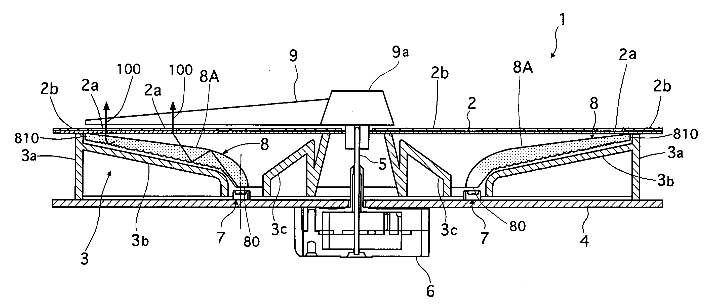
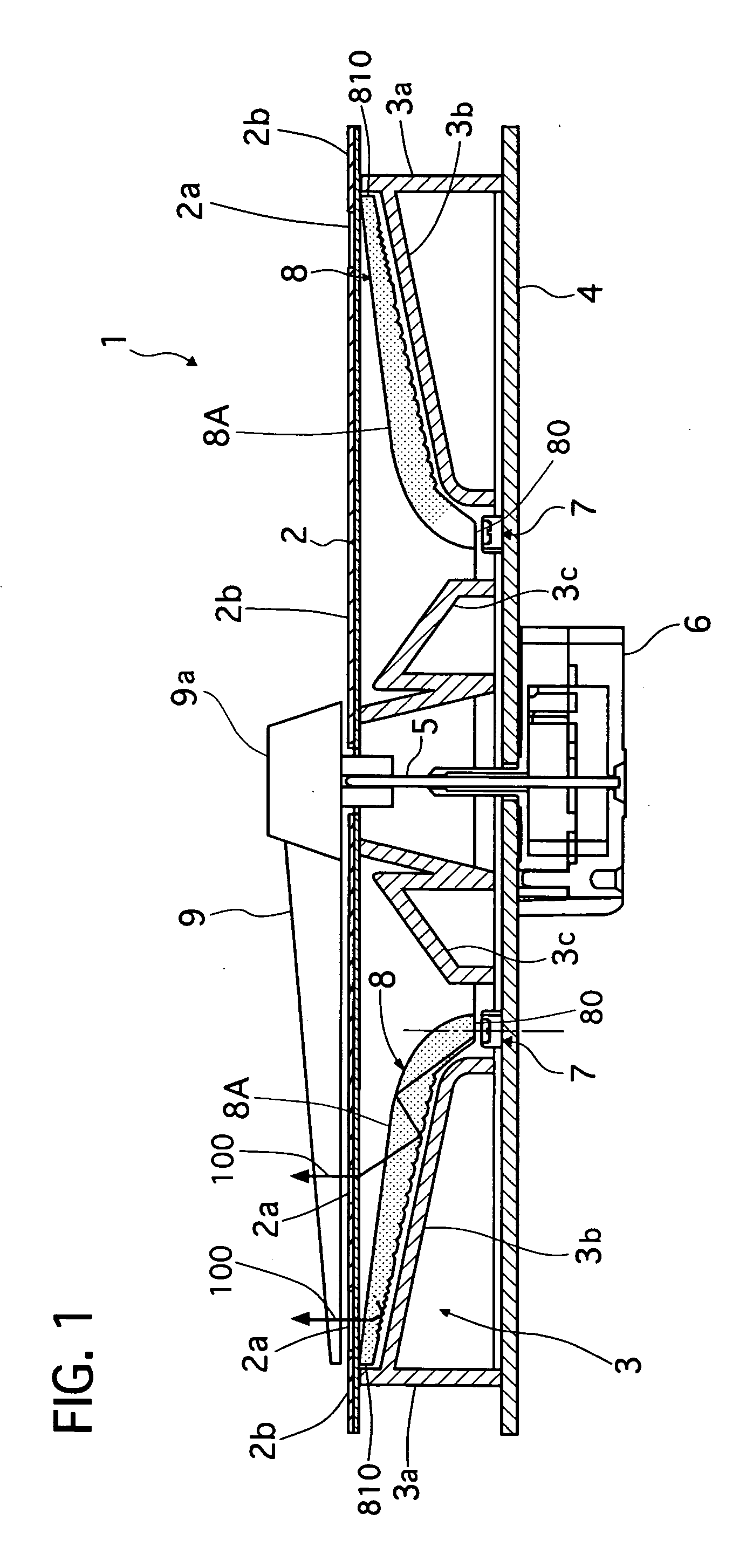
[0032]Referring to FIG. 1 of the drawing, there is shown an instrument device 1, installed on a not-shown instrument panel of a motor vehicle, having a lighting device of a preferred embodiment according to the present invention.

[0033]The instrument device 1 is a speed meter, a tachometer (an engine speed meter), a fuel meter and the like. The instrument device 1 has an indicator needle, display designed parts, including scale marks and characters, and a background, which are illuminated for enhancing visibility thereof. The device 1 includes a display plate 2 provided with display designed parts 2a and a background part 2b, a reflecting wall part 3, a base plate 4, the indicator needle 9, an indicator spindle 5, a spindle drive part 6, a plurality of light sources 7 and ...


PUM


Abstract

A lighting device, for illuminating display designed parts on a display plate, includes at least one light source arranged at a rear side of the display plate, and a light guide body having a light guide portion for guiding the light toward its outer-circumferential portion to output the light toward the display designed parts through a front surface of the light guide portion. The outer-circumferential portion has an outer-circumferential side wall surface at is outer end. The light guide portion has at least one projecting portion projecting from the outer-circumferential side wall surface. The projecting portion is provided with a reflecting side surface formed along the outer-circumferential side wall surface so that the reflecting side surface can reflect the light traveling in the light guide portion to be outputted through the front surface of the light guide portion.

Description

BACKGROUND OF THE INVENTION[0001]1. Field of the Invention[0002]The present invention relates to a lighting device that is capable of guiding light outputted from a light source toward an object or a portion to be irradiated, and in particular the invention is useful for a lighting device of an instrument of a motor vehicle.[0003]2. Description of the Related Art[0004]A conventional lighting device of this kind is disclosed in Japanese patent laid-open publication No. 2003-130693. This conventional lighting device is used for illuminating an indicator of a water temperature meter provided on an instrument panel of a motor vehicle for example, and it is equipped with a light source for emitting light and a light guide body for guiding the light toward an indicator needle and an indicator plate having display designed portions, such as scale marks and characters, arranged around a center axis of the indicator needle. The light source is arranged in the vicinity of a spindle of the ind...

Claims


Application Information

Patent Timeline
Patent Type & Authority Applications(United States)
IPC IPC(8): G01D11/28
CPCG02B6/0038G02B6/0045
Inventor TAMURA, KINYA
Owner CALSONIC KANSEI CORP
Why Eureka
Try Eureka