Relay server and relay communication system

a relay communication system and relay technology, applied in the field of relay servers, can solve the problems of inability to selectively set the terminal incapable of such exchange, the system tends to be rigid, and the inability to establish scalable and flexible systems

Active Publication Date: 2008-11-13
MURATA MASCH LTD
View PDF37 Cites 2 Cited by
  • Summary
  • Abstract
  • Description
  • Claims
  • Application Information

AI Technical Summary

Benefits of technology

[0009]In order to overcome the problems described above, preferred embodiments of the present invention provide a relay communication system in which a resource can be shared with and/or used by terminals. More...

Problems solved by technology

However, since a system of the above-described type establishes the network virtually, the system tends to be rigid.
Therefore, it is not easy to establish a scalable and flexible system.
For example, in a conventional communication system, a terminal capable of exchanging data between base points and a terminal incapable of such exchange cannot be selectively set at each base point.
Moreover, when a resource, such as a file, is sha...

Method used


Image

  • Relay server and relay communication system
  • Relay server and relay communication system
  • Relay server and relay communication system

Examples


Embodiment Construction

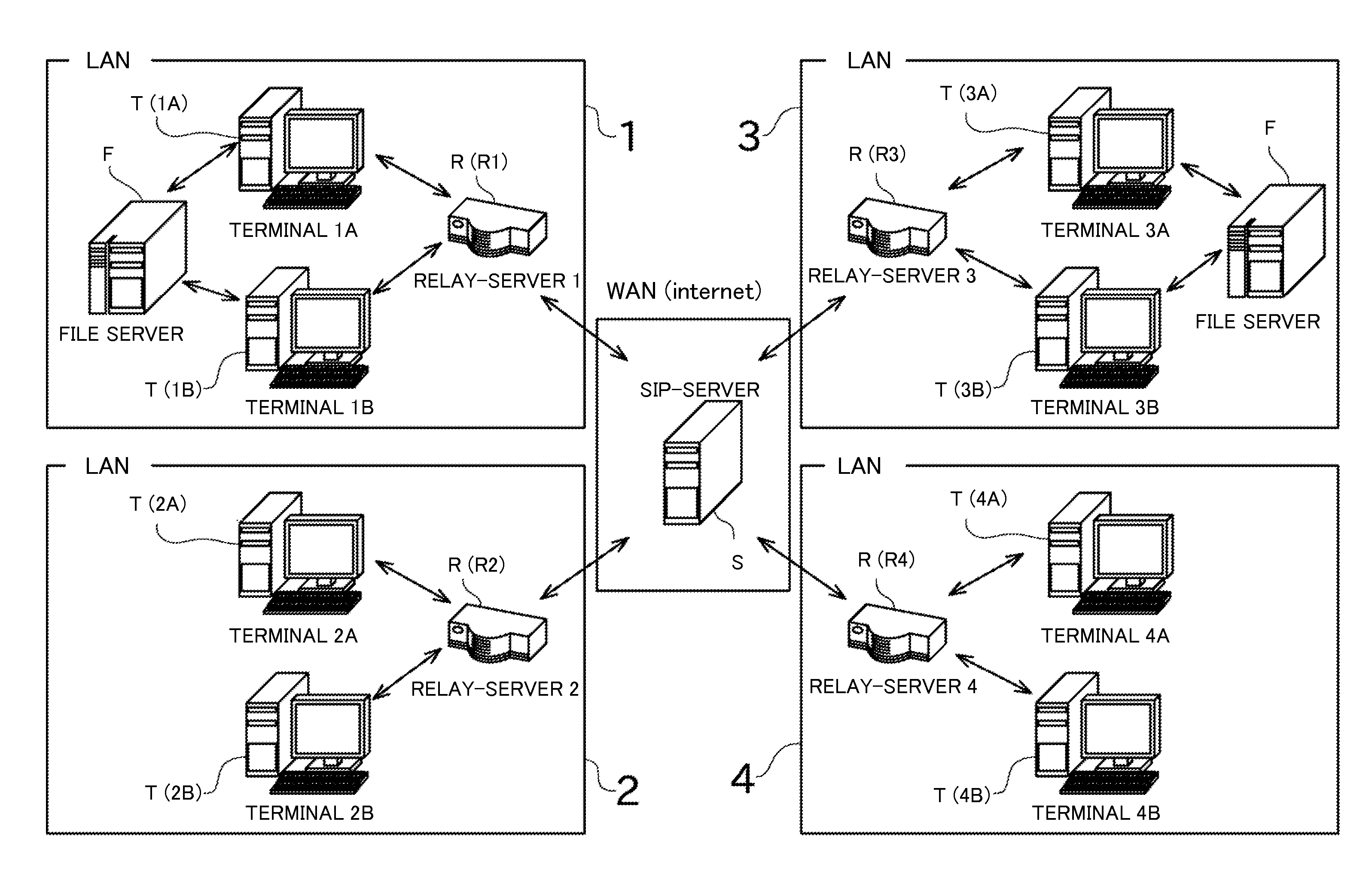
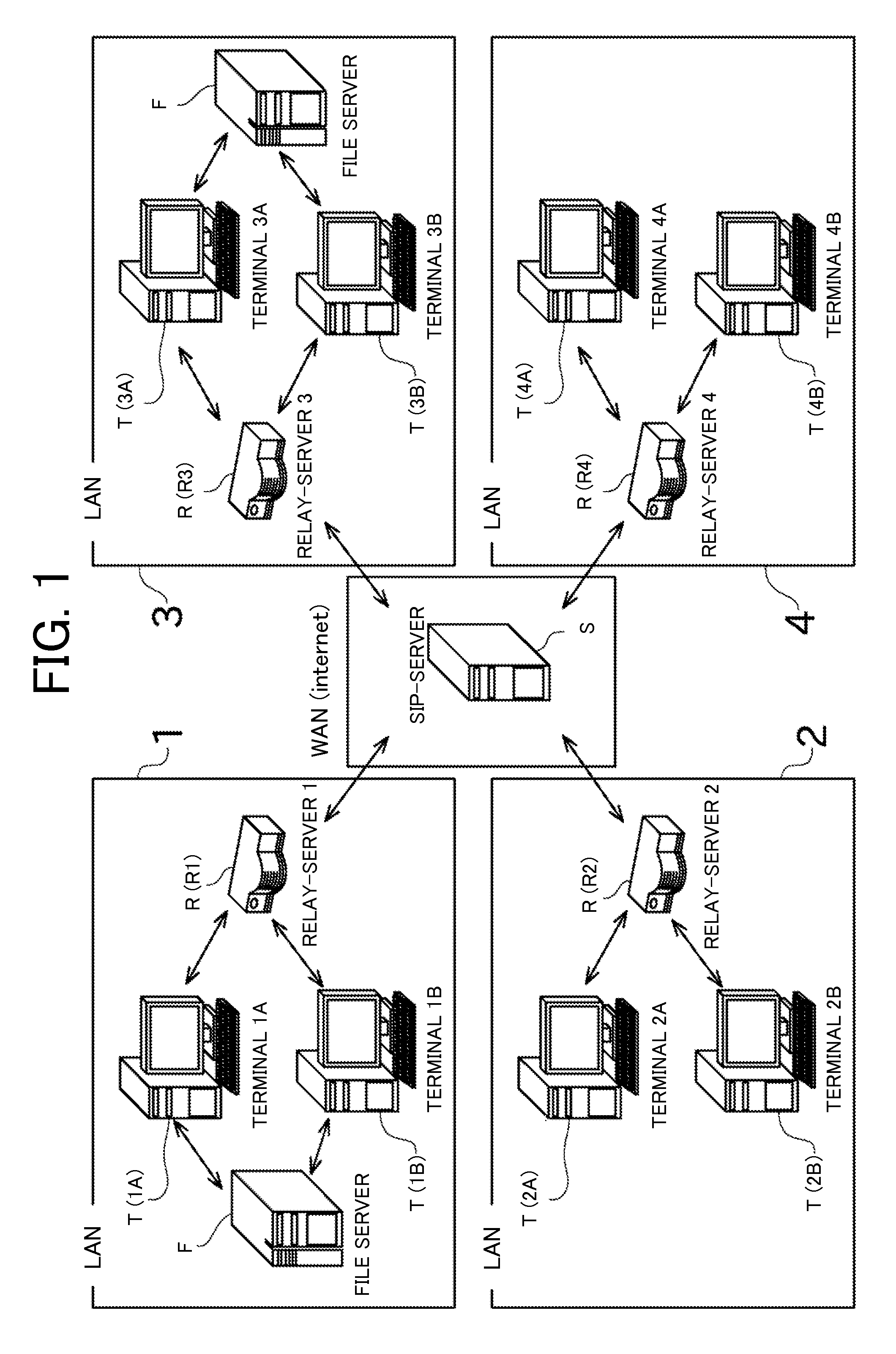
[0030]Preferred embodiments of the present invention will now be described with reference to the drawings. FIG. 1 is a diagram illustrating an overall configuration of a relay communication system according to a preferred embodiment of the present invention.

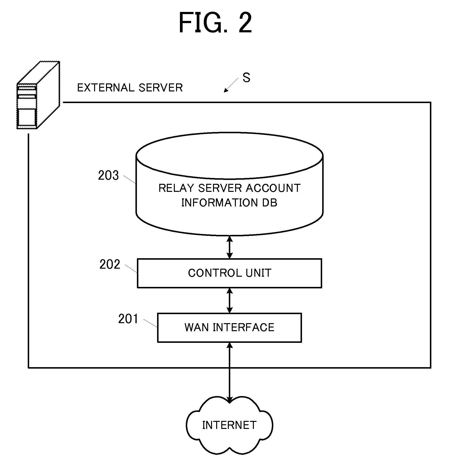
[0031]As illustrated in FIG. 1, the relay communication system includes a plurality of LANs connected to a Wide Area Network (WAN). The relay communication system includes an external server S, a relay server R, a client terminal T, and a file server F.

[0032]The WAN is a network that connects different LANs to each other. In the present preferred embodiment, the Internet is preferably used as the WAN.

[0033]The LAN is a relatively small-scale network provided in a limited location. A plurality of LANs is provided, each of which is provided at a physically remote location. In the present preferred embodiment, a LAN 1 is provided at a Tokyo branch office, and LANs 2, 3, 4 are respectively provided at an Osaka branch office, a Nagoya...


PUM


Abstract

A relay server is capable of communicating with other relay servers through an external server arranged on a Wide Area Network. The relay server stores information about a registered terminal, information about the relay servers forming a relay group by permitting connection among each other, and information about a resource and a client terminal sharing the resource. When an operation instruction regarding the resource in another terminal is received, the relay server relays the operation instruction from the registered terminal to another relay server. However, when key information is stored in association with the resource, the relay server relays the operation instruction to the other relay server only when a correct key has been entered.

Description

CROSS-REFERENCE TO RELATED APPLICATIONS[0001]This application claims priority under 35 U.S.C. 119 to Japanese Patent Application No. 2007-124708, filed on May 9, 2007, and Japanese Patent Application No. 2007-152121, filed on Jun. 7, 2007 which applications are hereby incorporated by reference in their entirety.BACKGROUND OF THE INVENTION[0002]1. Field of the Invention[0003]The present invention primarily relates to a relay server that enables communication between terminals.[0004]2. Description of the Related Art[0005]A communication technique referred to as a Virtual Private Network (VPN) is conventionally known. The VPN is used, for example, for communication over the Internet between terminals connected to a Local Area Network (LAN) of a plurality of branch offices (base points) established in multiple regions. Through the use of the VPN, another LAN in a remote location can be used as if it is a directly connected network.[0006]However, since a system of the above-described typ...

Claims


Application Information

Patent Timeline
IPC IPC(8): G06F15/16
CPCH04L63/083H04L63/101
Inventor TANIMOTO, YOSHIFUMI
Owner MURATA MASCH LTD
Why Eureka
Try Eureka