Light Emitting Device and Method for Driving the Same

a technology of light emitting device and light emitting device, which is applied in the direction of separation process, filtration separation, instruments, etc., can solve the problems of reducing the resistance of led, lcd monitor including 9 bars may have the problem of brightness or color deviation, and considerable heat generation

Inactive Publication Date: 2009-01-22
LG INNOTEK CO LTD
View PDF18 Cites 22 Cited by
  • Summary
  • Abstract
  • Description
  • Claims
  • Application Information

AI Technical Summary

Benefits of technology

[0021]According to an embodiment of the present invention, it is possible to provide a light emitting device capable of generating light of uniform brightness, taking into account characteristics of LEDs and characteristics of bars each including a plurality of LEDs.
[0022]According to an embodiment of the present invention, it is possible to provide a light emitting device adequate for a backlight light source of an LCD panel.

Problems solved by technology

The RGB LEDs disposed in the bars, however, are not uniform in chromaticity and brightness, causing deviation.
For example, an LCD monitor including 9 bars may have the problem of brightness or color deviation depending on screen positions thereof because the bars have different electric characteristics.
Furthermore, considerable heat is generated in the LED during the conversion of electrical energy to light, and resistance of the LED decreases with increasing temperature.
In addition, when electric power of substantially constant voltage is supplied to the LED, resistance of the LED decreases, which may lead to an increase of electric current, and thus to a more significant increase of heat generation.
Such an increased temperature deteriorates the LEDs, affects the performance of the LCD panel including LEDs as a light source, and thus makes it difficult to realize a desired color on the LCD panel.

Method used


Image

  • Light Emitting Device and Method for Driving the Same
  • Light Emitting Device and Method for Driving the Same
  • Light Emitting Device and Method for Driving the Same

Examples


Embodiment Construction

[0027]Reference will now be made in detail to the preferred embodiments of the present invention, examples of which are illustrated in the accompanying drawings. Wherever possible, the same reference numbers will be used throughout the drawings to refer to the same or like parts.

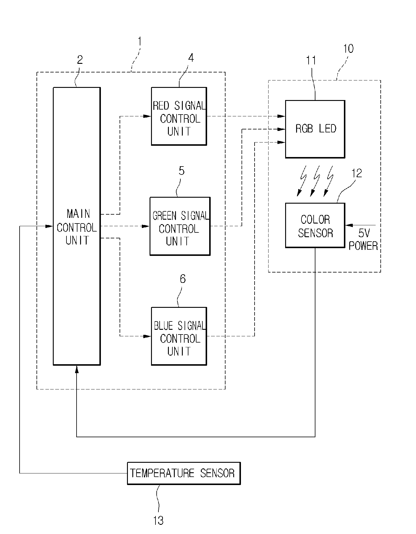
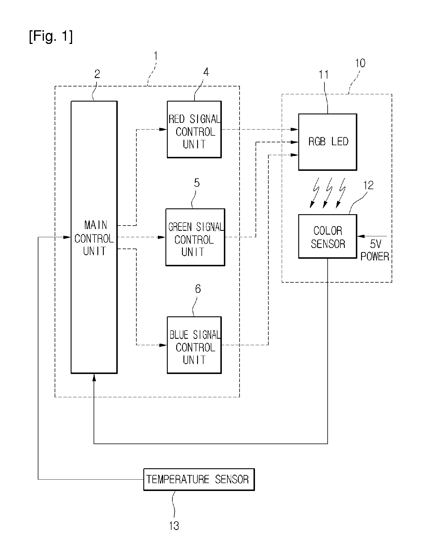
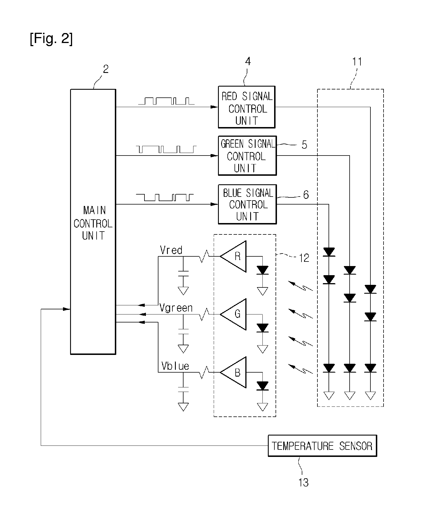
[0028]FIG. 1 is a block diagram illustrating a light emitting device according to an embodiment of the present invention. FIG. 2 is a block diagram illustrating how R, G and B LEDs are controlled and compensated for brightness deviations according to an embodiment of the present invention. FIG. 3 is a block diagram illustrating how LEDs in a plurality of bars are controlled and compensated for brightness deviations according to an embodiment of the present invention.

[0029]Referring to FIG. 1, an LED driver 1 includes a main control unit 2, a red signal control unit 4 for controlling R LEDs, a green signal control unit 5 for controlling G LEDs, and a blue signal control unit 6 for controlling B LEDs.

[0030]The...


PUM

PropertyMeasurementUnit
critical temperatureaaaaaaaaaa
coloraaaaaaaaaa
brightnessaaaaaaaaaa

Abstract

A light emitting device is provided. The light emitting device comprises a light emitting unit, a color sensor, a main control unit and a red, green and blue signal control unit. The light emitting unit has a red, a green and a blue LED. The color sensor senses a red, a green and a blue color signal value of light emitted from light emitting unit. The main control unit compares the red, green and blue color signal values with pre-stored target brightness values. Then, the main control unit outputs PWM duty values that have reflected the compensation brightness. The red, green and blue signal control unit drives the red, green and blue LED depending on the PWM duty values output from the main control unit.

Description

TECHNICAL FIELD[0001]The embodiment of the present invention relates to a lighting device and a method for driving the same.BACKGROUND ART[0002]Recently, a light emitting diode (LED) is widely used as a light source of a light emitting device. Particularly, the LED is used as a backlight light source of a liquid crystal display (LCD) panel.[0003]In that case, the backlight light source of the LCD panel includes a plurality of LEDs. A set of a red (R), a green (G) and a blue (B) LED is referred to as a cluster, a plurality of clusters mounted and arranged on a substrate is referred to as a bar, and a row of interconnected R, G or B LEDs in the bar is referred to as a string.[0004]As the LCD panel increases in size, a plurality of bars are used to accommodate an increased number of LEDs.[0005]The RGB LEDs disposed in the bars, however, are not uniform in chromaticity and brightness, causing deviation.[0006]Accordingly, a method for improving brightness and color gamut of a light sourc...

Claims


Application Information

Patent Timeline
Patent Type & Authority Applications(United States)
IPC IPC(8): G09G3/36
CPCG09G3/3413G09G3/342G09G3/3611G09G2360/145G09G2320/064G09G2320/0666G09G2320/041B01D25/12B01D25/30B01D25/32C02F11/122
Inventor PARK, SEONG SOOKIM, SUNG EUN
Owner LG INNOTEK CO LTD
Why Eureka
Try Eureka