

Method of manufacturing a lighting bollard assembly
- Summary
- Abstract
- Description
- Claims
- Application Information
AI Technical Summary
Benefits of technology
Problems solved by technology
Method used
Image

Examples
Embodiment Construction
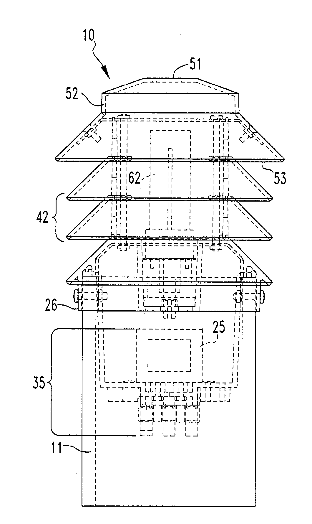
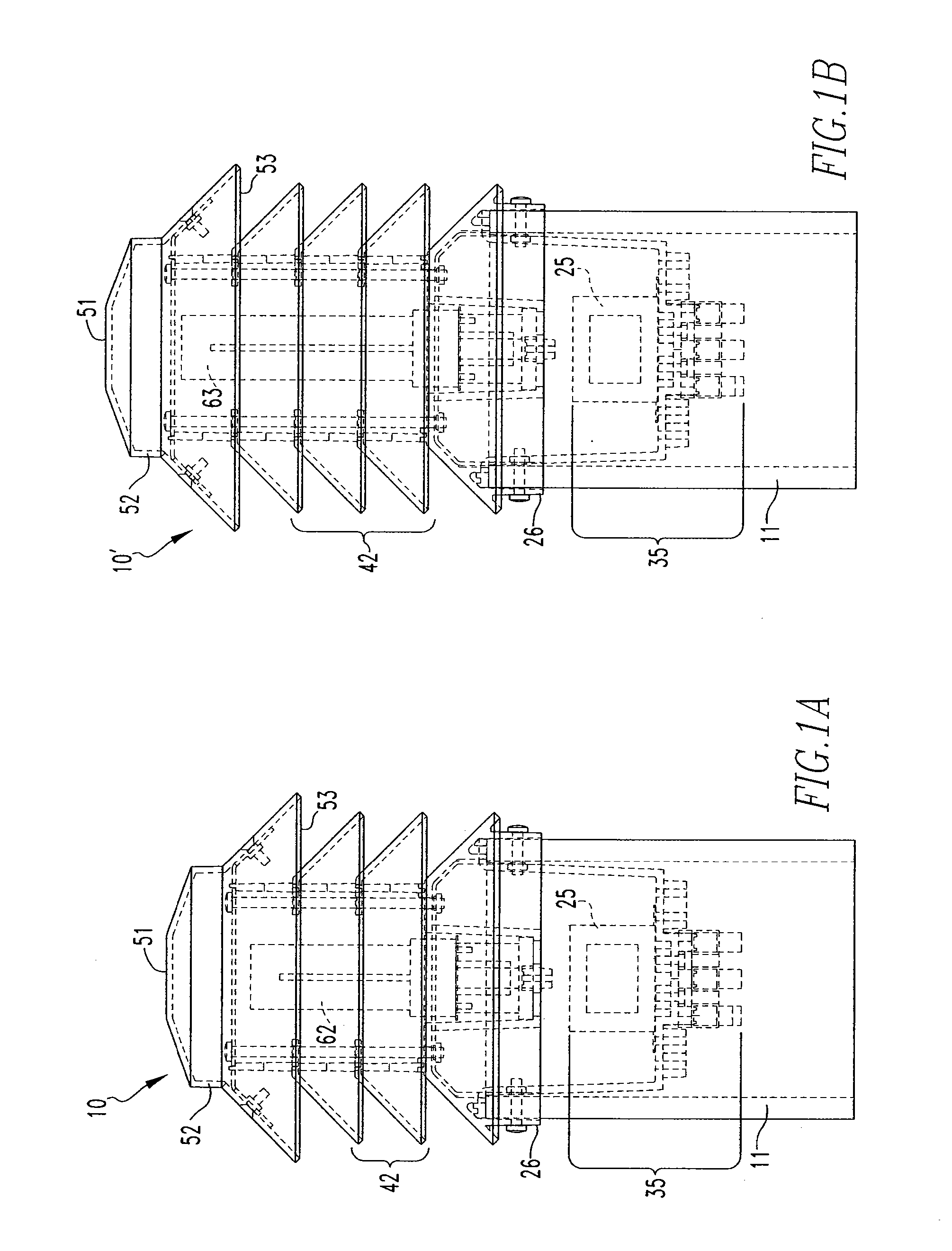
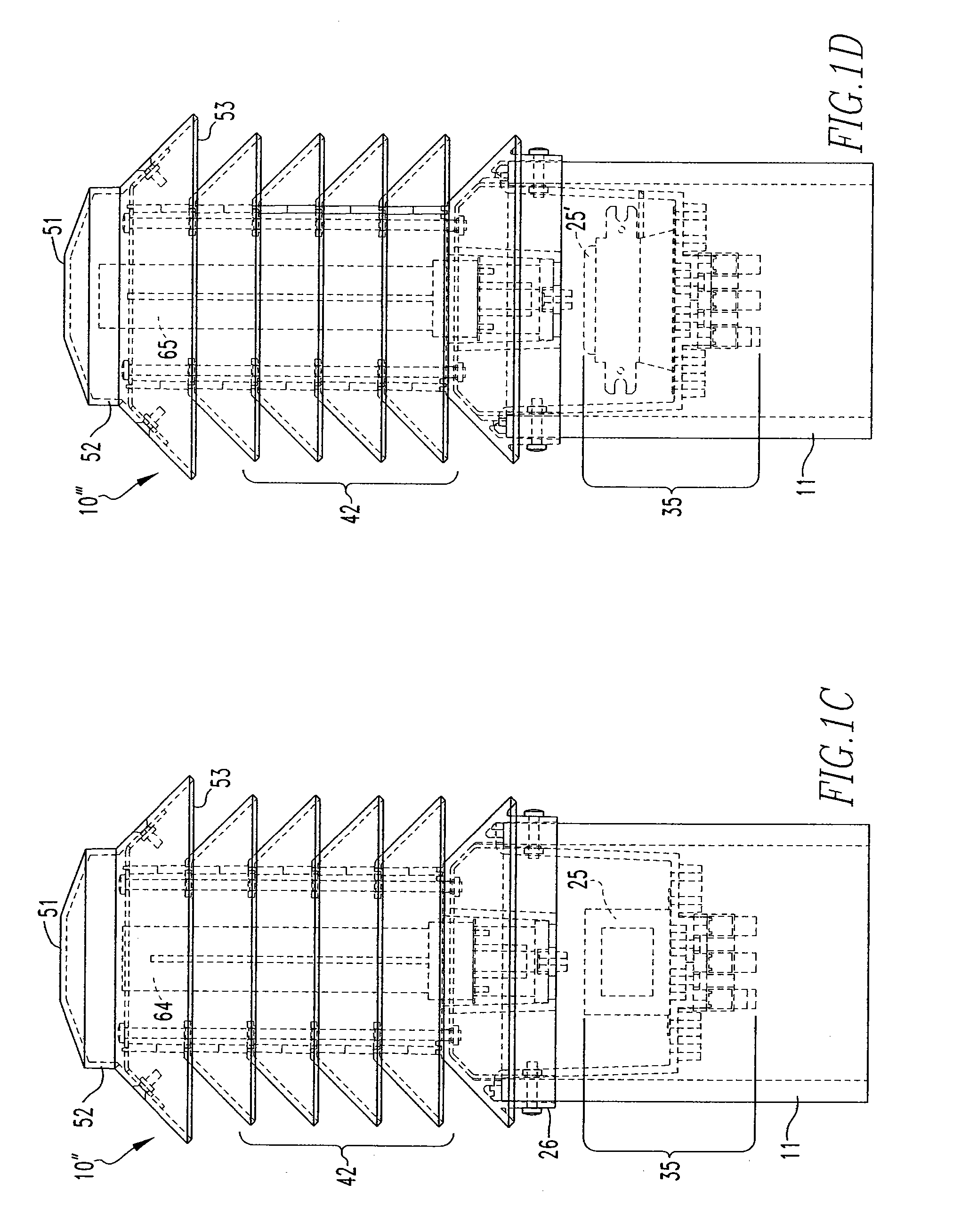
[0025]A complete understanding of the present invention will be obtained from the following description taken in connection with the accompanying drawing figures, wherein like reference characters identify like parts throughout.
[0026]Directional phrases used herein, such as, for example, “upper” and “lower” and derivatives thereof, relate to the orientation of the elements shown in the drawings and are not limiting upon the claims unless expressly recited therein.
[0027]As employed herein, the term “fastener” refers to any suitable connecting or tightening mechanism expressly including, but not limited to, screws, bolts and the combinations of bolts and nuts (e.g., without limitation, lock nuts) and washers and nuts.
[0028]As employed herein, the term “connector” refers to any suitable electrical connection or connection mechanism capable of carrying an electrical current therein.
[0029]As employed herein, the statement that two or more parts are “connected” or “coupled” together shall...
PUM
| Property | Measurement | Unit |
|---|---|---|
| Angle | aaaaa | aaaaa |
| Power | aaaaa | aaaaa |
| Power | aaaaa | aaaaa |
Abstract
Description
Claims
Application Information