Liquid crystal display device

Inactive Publication Date: 2009-02-12
PANASONIC LIQUID CRYSTAL DISPLAY CO LTD
View PDF8 Cites 3 Cited by
  • Summary
  • Abstract
  • Description
  • Claims
  • Application Information

AI Technical Summary

Benefits of technology

[0013]Accordingly, it is an object of the present invention to provide a liquid crystal display device which can realize further sufficient heat radiation efficiency.

Problems solved by technology

This implies that, with respect to the above-mentioned frame, when priority is assigned to a function to be performed by the frame, the selection of a material of the frame is limited and hence, there may be a case that the frame is required to be made of a material which exhibits unfavorable thermal conductivity.

Method used


Image

  • Liquid crystal display device
  • Liquid crystal display device
  • Liquid crystal display device

Examples


Embodiment Construction

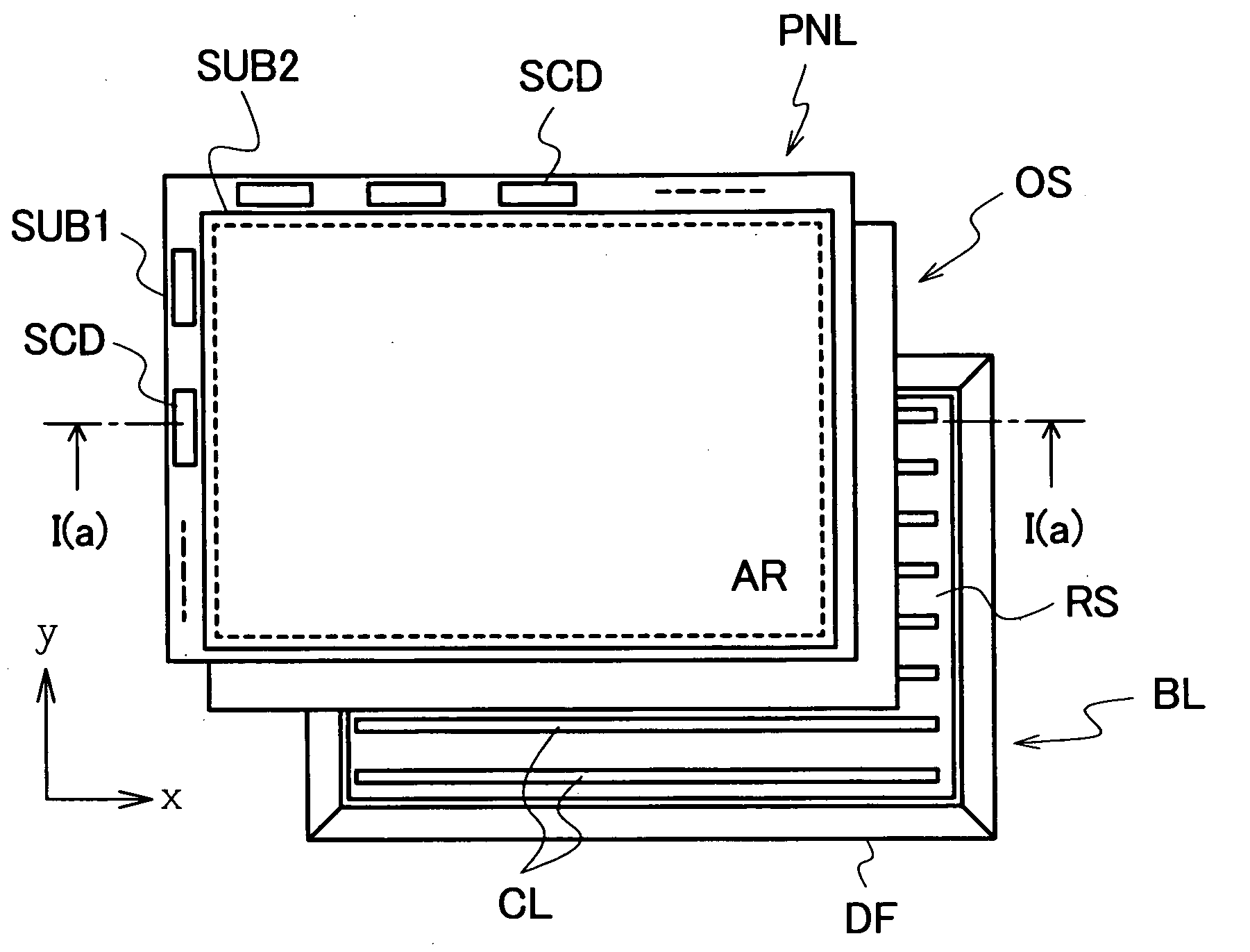
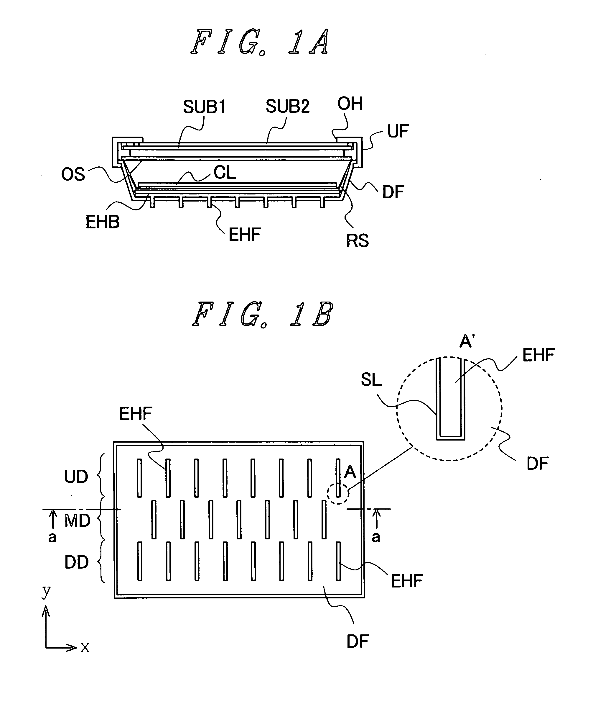
[0021](1) The present invention provides, for example, a liquid crystal display device which at least includes: a liquid crystal display panel; and a backlight arranged on a back surface of the liquid crystal display panel, the backlight including a plurality of rod-shaped light sources which is arranged parallel to each other in plane which faces the liquid crystal display panel in an opposed manner, wherein a frame which supports the rod-shaped light sources, a heat radiation plate arranged on a surface of the frame, through holes are formed in the frame, and heat radiation fins are formed on the heat radiation plate in a state that the heat radiation fins project from a surface of the frame on a side opposite to the liquid crystal display panel through the through holes.

[0022](2) In the liquid crystal display device of the present invention having the constitution (1), for example, a reflection sheet is arranged on a surface of the heat radiation plate on a liquid crystal display...


PUM


Abstract

A liquid crystal display device includes a liquid crystal display panel and a backlight arranged on a back surface of the liquid crystal display panel, the backlight including a plurality of rod-shaped light sources, a frame which supports the rod-shaped light sources, and a heat radiation plate which is arranged on an inner surface of the frame. Through holes are formed in the frame, and heat radiation fins are formed on the heat radiation plate in a state that the heat radiation fins project toward a back surface of the liquid crystal display panel through the through holes formed in the frame. Due to such a constitution, it is possible to provide a liquid crystal display device which can enhance heat radiation efficiency.

Description

CROSS-REFERENCE TO RELATED APPLICATION[0001]The present application claims priority from Japanese application JP2007-205351 filed on Aug. 7, 2007, the content of which is hereby incorporated by reference into this application.BACKGROUND OF THE INVENTION[0002]1. Field of the Invention[0003]The present invention relates to a liquid crystal display device, and more particularly to a liquid crystal display device having a so-called direct-type backlight.[0004]2. Description of the Related Art[0005]With respect to a liquid crystal display device, along with a demand for large-sizing of a liquid crystal display panel, as a backlight, a so-called direct-type backlight which can make a planar light source uniform has been used.[0006]The backlight is constituted of a plurality of rod-shaped light sources formed of, for example, fluorescent lamps which are arranged parallel to each other in plane which faces the liquid crystal display panel in an opposed manner, a frame which supports these r...

Claims


Application Information

Patent Timeline
IPC IPC(8): G02F1/13357G02F1/1333
CPCG02F2001/133628G02F1/133604G02F1/133628
InventorNAGAOKA, MASAFUMITANAKA, KAZUYOSHITEZUKA, AKIOOTA, TAKAYUKI
OwnerPANASONIC LIQUID CRYSTAL DISPLAY CO LTD