Cyclone dust collecting apparatus for vacuum cleaner

Active Publication Date: 2009-05-28
SAMSUNG GWANGJU ELECTRONICS CO LTD
View PDF21 Cites 66 Cited by
  • Summary
  • Abstract
  • Description
  • Claims
  • Application Information

AI Technical Summary

Benefits of technology

[0012]The present disclosure has been developed in order to overcome the above drawbacks and other problems associated with the conventional arrangement. An aspect of the present disclosure is to

Problems solved by technology

However, the conventional cyclone dust collecting apparatus cannot separate fine dust well from the dust-laden air because there is little difference between weights of the fine dust and the ai

Method used


Image

  • Cyclone dust collecting apparatus for vacuum cleaner
  • Cyclone dust collecting apparatus for vacuum cleaner
  • Cyclone dust collecting apparatus for vacuum cleaner

Examples


first embodiment

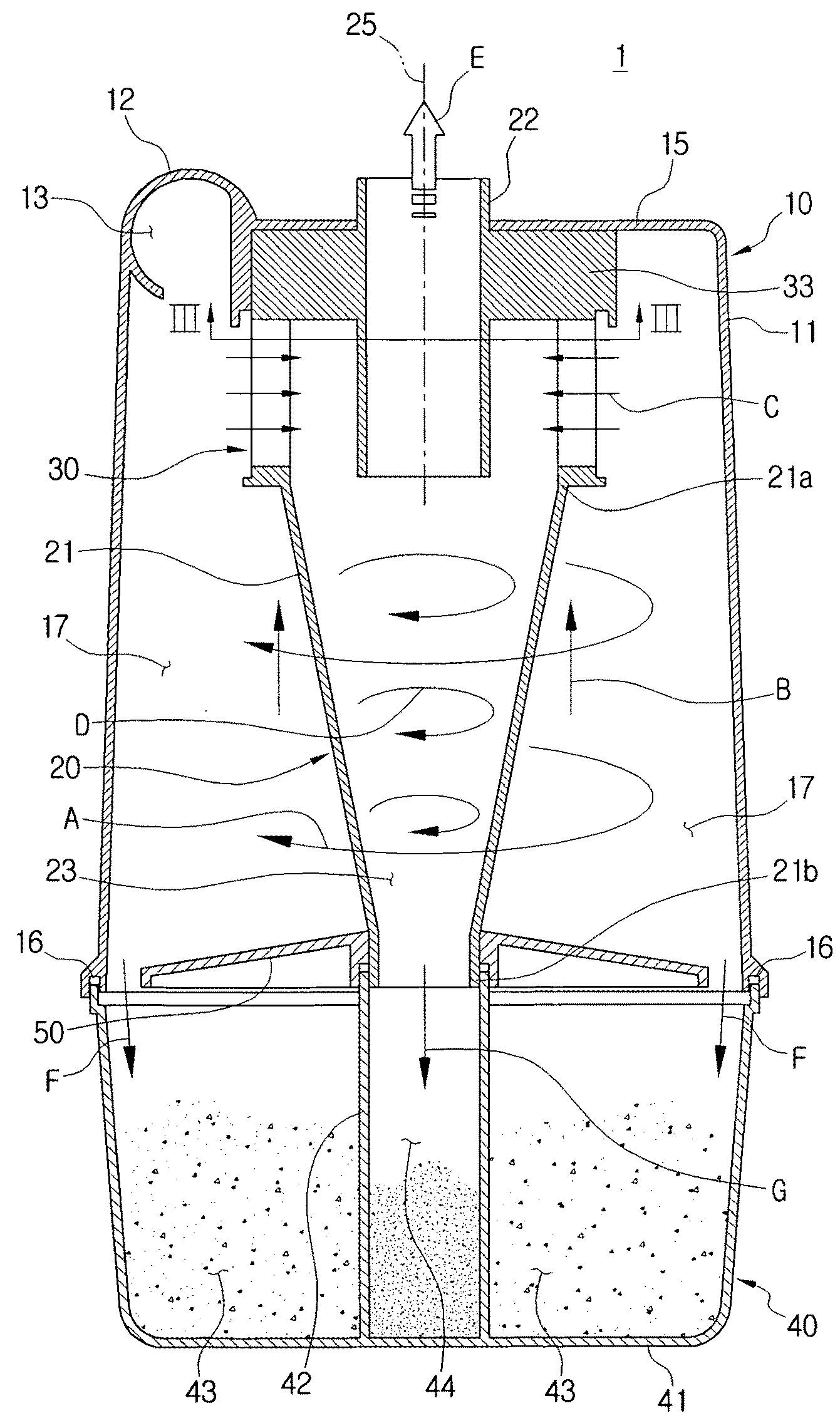
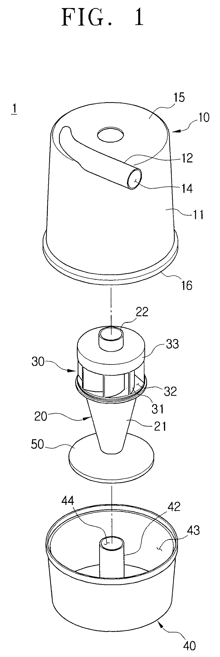
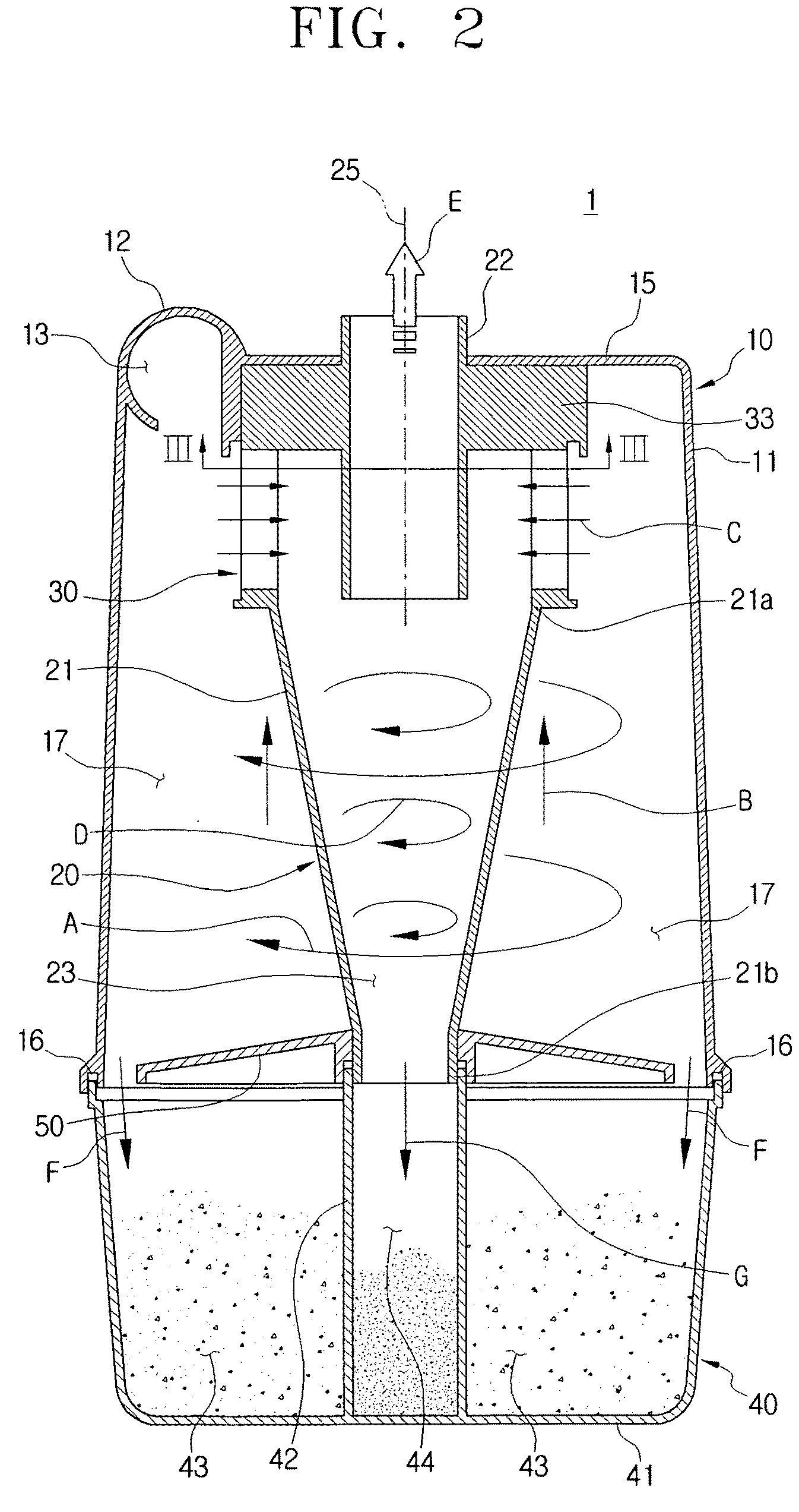
[0052]Referring to FIGS. 1 and 2, a cyclone dust collecting apparatus 1 for a vacuum cleaner according to the present disclosure includes a first cyclone 10, a second cyclone 20, and a dust collecting receptacle 40.

[0053]The first cyclone 10 draws-in outside air containing dust, dirt, and so on (hereinafter, referred to as dust-laden air), and forces the dust-laden air to downwardly whirl inside the first cyclone 10 so that dust, dirt and so on (hereinafter, referred to as dust) is separated from the dust-laden air by centrifugal force. Then, the first cyclone 10 discharges air having dust partially removed (hereinafter, referred to as semi-clean air) to the second cyclone 20.

[0054]The first cyclone 10 has a first cyclone body 11 and an air suction pipe 12. The first cyclone body 11 is formed in a substantially hollow cylindrical shape with a top end closed by a top wall 15 and an opened bottom end. At an upper side of the first cyclone body 11 is formed an air suction hole 13 throu...

second embodiment

[0069]Hereinafter, a cyclone dust collecting apparatus 2 for a vacuum cleaner according to the present disclosure is explained with reference to FIGS. 5 to 8D.

[0070]Referring to FIGS. 5 and 6, a cyclone dust collecting apparatus 2 for a vacuum cleaner according to the second embodiment of the present disclosure includes a first cyclone 10, a second cyclone 20′, and a dust collecting receptacle 40.

[0071]The cyclone dust collecting apparatus 2 according to the second embodiment has the same first cyclone 10 and dust collecting receptacle 40 as those of the cyclone dust collecting apparatus 1 according to the first embodiment as described above except the second cyclone 20′. Therefore, the second cyclone 20′ is only described hereinafter.

[0072]The second cyclone 20′ is disposed inside the first cyclone 10, takes the semi-clean air C discharged from the first cyclone 10, and forces the semi-clean air C to form the second downwardly whirling air current D. Then, fine dust is separated fr...

third embodiment

[0081]Hereinafter, a cyclone dust collecting apparatus 3 for a vacuum cleaner according to the present disclosure is described with reference to FIGS. 9 and 10.

[0082]Referring to FIGS. 9 and 10, a cyclone dust collecting apparatus 3 for a vacuum cleaner according to the third embodiment of the present disclosure includes a first cyclone 110, a second cyclone 120, a filtering member 100, and a dust collecting receptacle 140.

[0083]The first cyclone 110 is substantially the same as the first cyclone 10 of the cyclone dust collecting apparatus 1 according to the first embodiment, exception that the air-discharging pipe 117 is disposed at a top wall 15 of the first cyclone body 11. The air-discharging pipe 117 discharges purified air E passed through the filtering member 100 to the vacuum generator (not shown).

[0084]The second cyclone 120 is disposed inside the first cyclone 110. The semi-clean air C discharged from the first cyclone 110 enters to form a second downwardly whirling air cu...


PUM


Abstract

A cyclone dust collecting apparatus for a vacuum cleaner includes a first cyclone, a second cyclone disposed inside the first cyclone, and an air guiding member to form an entrance of the second cyclone through which semi-clean air discharged from the first cyclone enters. The air guiding member includes a grill member to have a plurality of holes, and a plurality of guiding blades disposed inside the grill member.

Description

CROSS-REFERENCE TO RELATED APPLICATIONS[0001]This application is a continuation-in-part of U.S. patent application Ser. No. 11 / 494,211, filed Jul. 27, 2006, which claims priority to U.S. provisional patent application No. 60 / 776,408 filed Feb. 24, 2006 in the United States Patent & Trademark Office, and claims the benefit under 35 U.S.C. § 119(a) from Korean Patent Application No. 2006-20961, filed Mar. 6, 2006 and No. 2006-31518 filed Apr. 6, 2006 in the Korean Intellectual Property Office, the disclosures of all of which are incorporated herein by reference in their entirety.BACKGROUND OF THE INVENTION[0002]1. Field of the Invention[0003]The present disclosure relates to a vacuum cleaner. More particularly, the present disclosure relates to a cyclone dust collecting apparatus separating and collecting dust and dirt using centrifugal force.[0004]2. Description of the Related Art[0005]Generally, a vacuum cleaner generates suction force using a motor so as to draw-in air containing d...

Claims


Application Information

Patent Timeline
IPC IPC(8): B04C5/26
CPCA47L9/1633A47L9/165B01D45/16A47L9/1683A47L9/1666Y10S55/03
Inventor YOO, DONG-HUNOH, JANG-KEUNHAN, JUNG-GYUN
Owner SAMSUNG GWANGJU ELECTRONICS CO LTD
Why Eureka
Try Eureka