Image display aparatus

a technology of image display and apparatus, applied in the direction of instruments, optical light guides, optics, etc., can solve the problems of stepping region, radiation of heat, small light source, etc., and achieve the effect of high brightness

Inactive Publication Date: 2009-09-17
PANASONIC CORP
View PDF7 Cites 12 Cited by
  • Summary
  • Abstract
  • Description
  • Claims
  • Application Information

AI Technical Summary

Benefits of technology

[0009]Thus, an object of the present invention is to solve such problems and provide a long-lifespan image display apparatus that gives an adjustable brightness, realizes a high brightness, and exhibits an even luminous intensity distribution.
[0017]According to this structure, the distance between the central axis of light-radiation of the LED element and the reflective sheet is short, so that in an end portion of the light conducting plate, the interval between the following can be made short: light reflected on the reflective sheet and then radiated out from the light conducting plate, and light transmitted through the light conducting plate. Thus, the length of the end region of the light conducting plate for causing light to be evenly radiated into the liquid crystal panel region can be made small. Therefore, the frame (or trim) region of the image display apparatus is made small so that the whole of the image display apparatus can be made small.
[0022]According to this structure, a large number of LED elements can be arranged. The control of an input to each of the LED elements makes it possible to provide an image display apparatus wherein brightness can be adjusted and a high brightness is realized.
[0026]According to this structure, heat generated from individual LED elements of the upper and lower LED elements can be effectively radiated so that an input to each of the LED elements can easily be controlled.

Problems solved by technology

However, in recent years, LED elements as light sources have been becoming smaller and the power thereof has been becoming higher.
However, if a small-sized LED element is formed in such a manner that its LED element substrate is stepped in order to make the central axis of the LED element consistent with the middle surface of its light conducting plate, a problem that radiation of heat is blocked by the stepped region, and other problems are caused.

Method used


Image

  • Image display aparatus
  • Image display aparatus
  • Image display aparatus

Examples


first embodiment

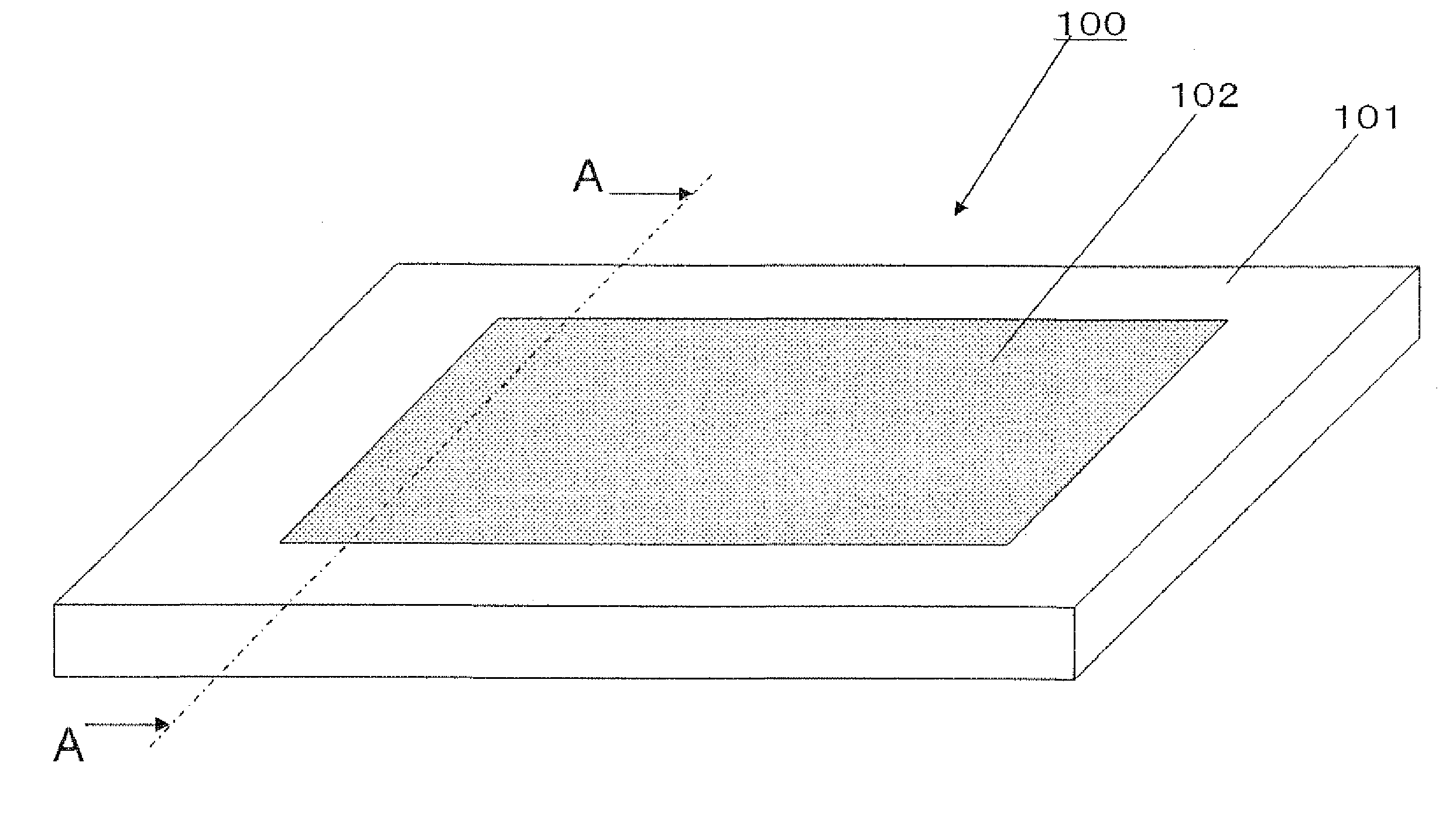
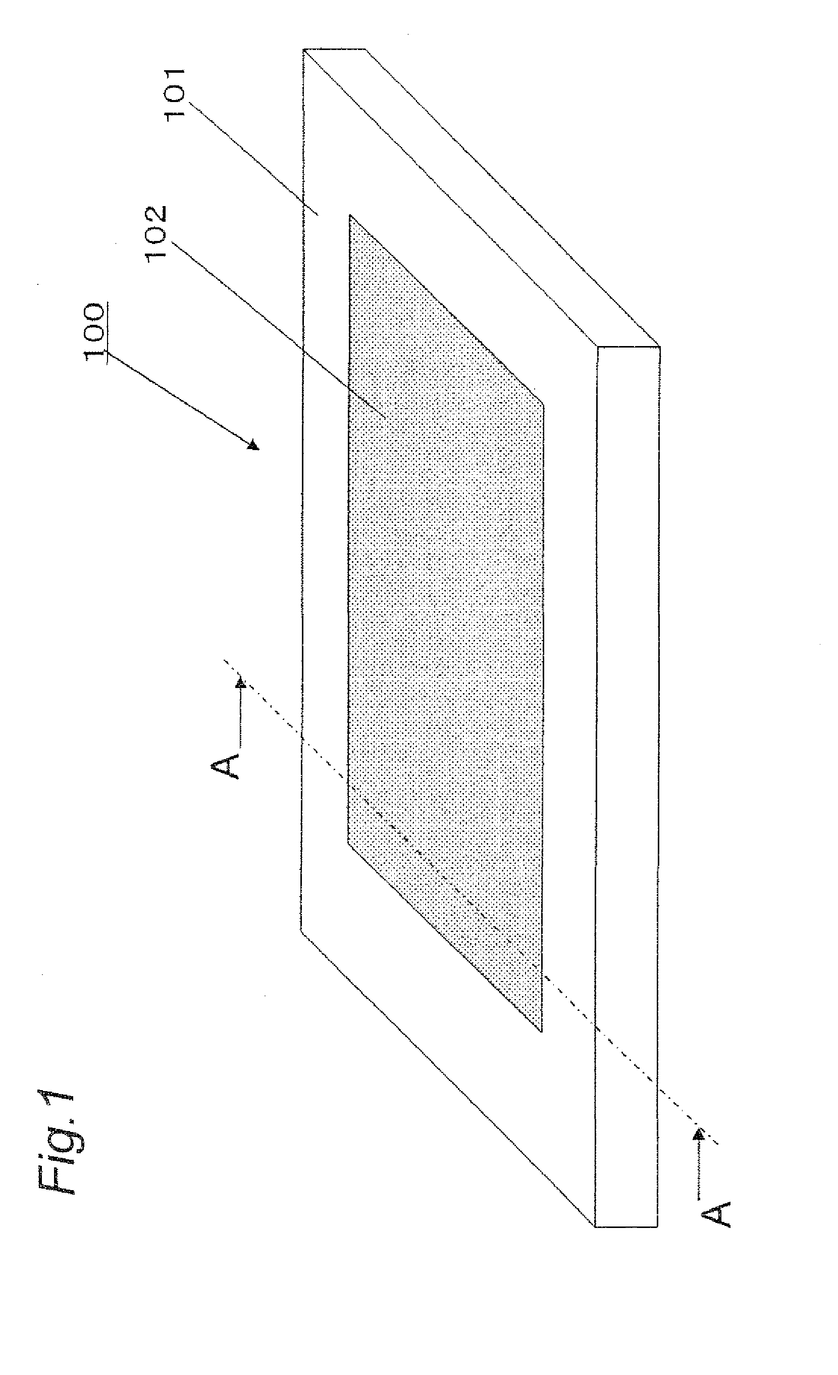
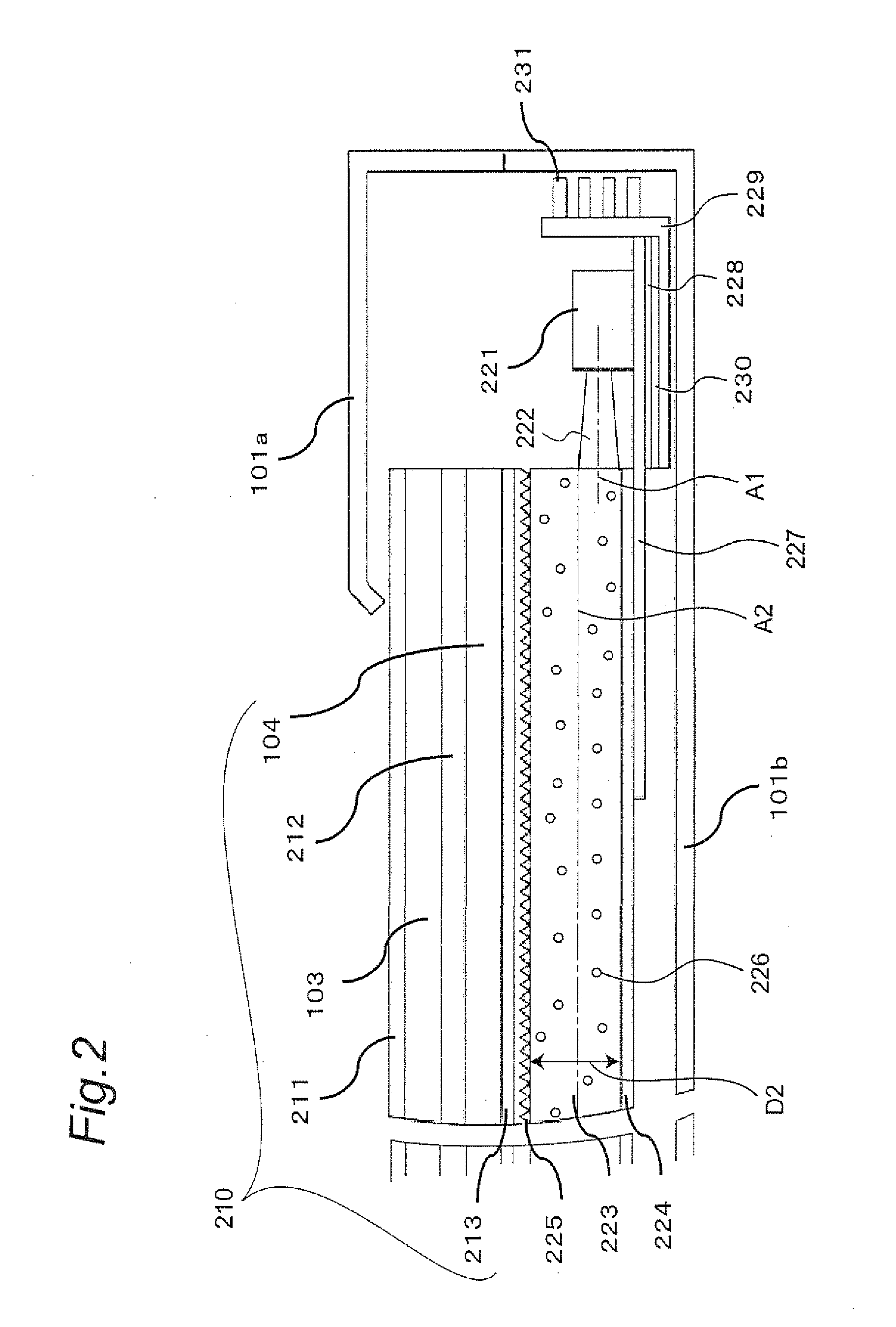
[0039]FIG. 1 is a perspective view that schematically illustrates an image display apparatus according to a first embodiment, and FIG. 2 is a partial sectional view taken along line A-A of FIG. 1. As illustrated in FIG. 1, in an image display apparatus 100, which is the apparatus, the periphery thereof is surrounded by a housing 101 made of resin, and a liquid crystal panel 102 is arranged therein. As illustrated in FIG. 2, the liquid crystal panel 102 is made up of a liquid crystal display unit and a backlight source unit. The liquid crystal display unit is equipped with a front surface glass substrate 103, a rear surface glass substrate 104, a liquid crystal body region 212 arranged between the front and rear surface glass substrates 103 and 104, a light-ejection-side polarizing plate 211 disposed on the front surface glass substrate 103, and a light-incident-side polarizing plate 213 disposed on the rear surface glass substrate 104. Furthermore, the backlight source unit is made ...

second embodiment

[0051]FIG. 5 is a partial sectional view illustrating the structure of a backlight source unit of an image display apparatus according to a second embodiment. The image display apparatus according to the second embodiment has the same basic structure as the image display apparatus 100 described in the first embodiment while the apparatus is different from the first embodiment in LED-arrangement. Specifically, as illustrated in FIG. 4, in the second embodiment, the LED element 221 is arranged relatively to the middle surface A2 between the front surface and the bottom surface of the light conducting plate 223 in such a manner that both end portions of the light emitting surface B of the LED element 221 in the thickness direction of the light conducting plate 223 are included into the front surface side of the light conducting plate 223. This point is different.

[0052]In the image display apparatus according to the second embodiment, the LED element 221 is disposed on the front surface...

third embodiment

[0053]FIG. 6 is a partial sectional view illustrating the structure of a backlight source unit of an image display apparatus according to a third embodiment. The image display apparatus according to the third embodiment has the same basic structure as the image display apparatus 100 described in the first embodiment while the apparatus is different from the first embodiment in LED-arrangement. Specifically, as illustrated in FIG. 6, in the third embodiment, two tiers of an upper LED element 221a and a lower LED element 221b are arranged, as the LED element 221, in the thickness direction of the light conducting plate 223. In this case, the central axis A1 of the light emitting surface B for light-radiation of the upper LED element 221a and the lower LED element 221 b is shifted from the middle surface A2 in the thickness direction of the light conducting plate 223. More specifically, the upper LED element 221a is arranged relatively to the middle surface A2 of the light conducting p...


PUM


Abstract

An image display apparatus including a liquid crystal display unit having a display surface and rear surface facing a display surface, a light conducting plate having a front surface, a bottom surface facing the front surface, and a side end surface perpendicular to the front surface and the bottom surface, the light conducting plate being arranged to face the rear surface of the liquid crystal display unit, the front surface of the light conducting plate facing the rear surface of the liquid crystal display unit, wherein the light conducting plate has a reflective sheet on the bottom surface, wherein incident light from a side end surface of the plate is reflected on the reflective sheet on the bottom surface so as to be conducted toward the front surface, and an LED element that has a light emitting surface facing the side end surface of the light conducting plate, for radiating light from the light emitting surface to the side end surface, wherein the LED element is arranged in the manner that the central axis of the light emitting surface of the LED element is shifted onto either of the bottom surface side or the front surface side of the light conducting plate from the middle surface of the light conducting plate between the front surface and the bottom surface of the light conducting plate.

Description

BACKGROUND OF THE INVENTION[0001]The present application claims the priority of Japanese Patent Application No. 2008-63665 filed on Mar. 13, 2008 in Japan, and that of Japanese Patent Application No. 2009-49343 filed on Mar. 3, 2009 in Japan, and the contents of which are incorporated herein by reference.TECHNICAL FIELD OF THE INVENTION[0002]The present invention relates to an image display apparatus having a backlight source, in particular, an image display apparatus having an LED element as its backlight source.DESCRIPTION OF THE PRIOR ART[0003]In the main current of image display apparatuses in recent years, liquid crystal has been used. In the apparatuses, images are displayed by transmitting light radiated into their liquid crystal panel from a backlight arranged on the rear surface side of the panel, wherein TFTs are formed on a glass piece and a liquid crystal is confined. Therefore, in order to obtain a bright and beautiful high-quality image, it is essential that the backli...

Claims


Application Information

Patent Timeline
Patent Type & Authority Applications(United States)
IPC IPC(8): G09G3/36
CPCG02B6/0041G02B6/0091G02B6/0085G02B6/0053
Inventor HATAKEYAMA, ATSUSHIFUJITA, SHINJI
Owner PANASONIC CORP
Why Eureka
Try Eureka