Protective Device with End-Of-Life Indication Before Power Denial
Inactive Publication Date: 2009-10-08
PASS SEYMOUR
View PDF33 Cites 44 Cited by
Summary
Abstract
Description
Claims
Application Information
AI Technical Summary
This helps you quickly interpret patents by identifying the three key elements:
Problems solved by technology
Method used
Benefits of technology
Benefits of technology
[0013]The present invention provides a variety of methods for indicating that an end-of-life, or device failure, has occurred. In one embodiment, the indicator is actuated automatically by a self-test mechanism that automatically identifies an end-of-life condition. In an another metho
Problems solved by technology
The protective device permanently denies power to the load terminals after the predetermined amount of time has elapsed.
While the user may be able to reset the protecti
Method used
Image
Click on the blue label to locate the original text in one second.
Reading with bidirectional positioning of images and text.
Examples
second embodiment
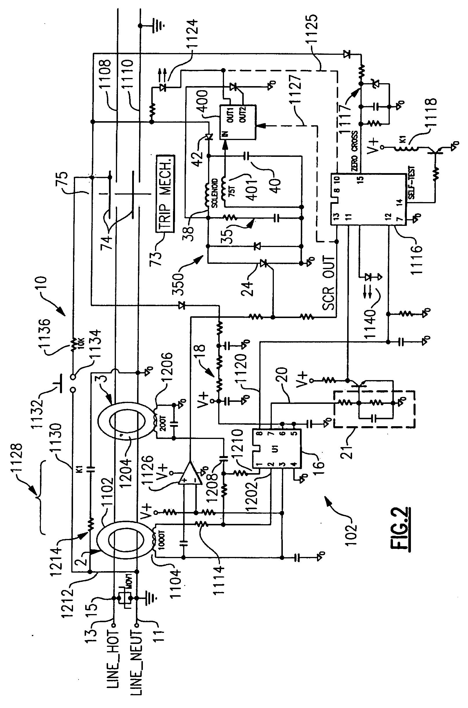
[0051]As embodied herein and depicted in FIG. 2, a schematic of a circuit protection device in accordance with the present invention is disclosed. FIG. 2 is a schematic diagram of an alternate embodiment in which the fault simulation circuit generates a simulated negative half cycle grounded neutral signal. Reference is made to U.S. patent application Ser. No. 10 / 768,530, which is incorporated herein by reference as though fully set forth in its entirety, for a more detailed explanation of the fault simulation signal. Note that test circuit 1128 does not include diode 4.
[0052]The GFI circuit 102 in FIG. 2 includes a transformer 2 that is configured to sense a load-side ground fault when there is a difference in current between the hot and neutral conductors. Transformer 2 transmits a sensed signal to detector circuit 16. GFI circuit 102 also includes a grounded neutral transmitter 3 that is configured to detect grounded neutral conditions. Those skilled in the art understand that th...
third embodiment
[0059]As embodied herein and depicted in FIG. 3, a schematic of a circuit protection device in accordance with the present invention is disclosed. FIG. 3 is a schematic diagram that illustrates how the present invention may be applied to a general protective device 300. Further, FIG. 3 incorporates a redundant solenoid.
[0060]If sensor 1302 is included, the protective device is an AFCI. If transformers 2 and 3 are included, the protective device is a GFCI. If sensor 1302, and transformers 2 and 3 are included, the protective device is a combination AFCI-GFCI. Stated generally, the protective device may include one or more, or a combination of sensors configured to sense one or more type of hazardous conditions in the load, or in the AC electrical circuit supplying power to the load. Sensor 1302 senses an arc fault signature in load current. Detector 1304 is similar to ground fault detector 16, but is configured to detect signals from any of the variety of sensors employed in the desi...
fourth embodiment
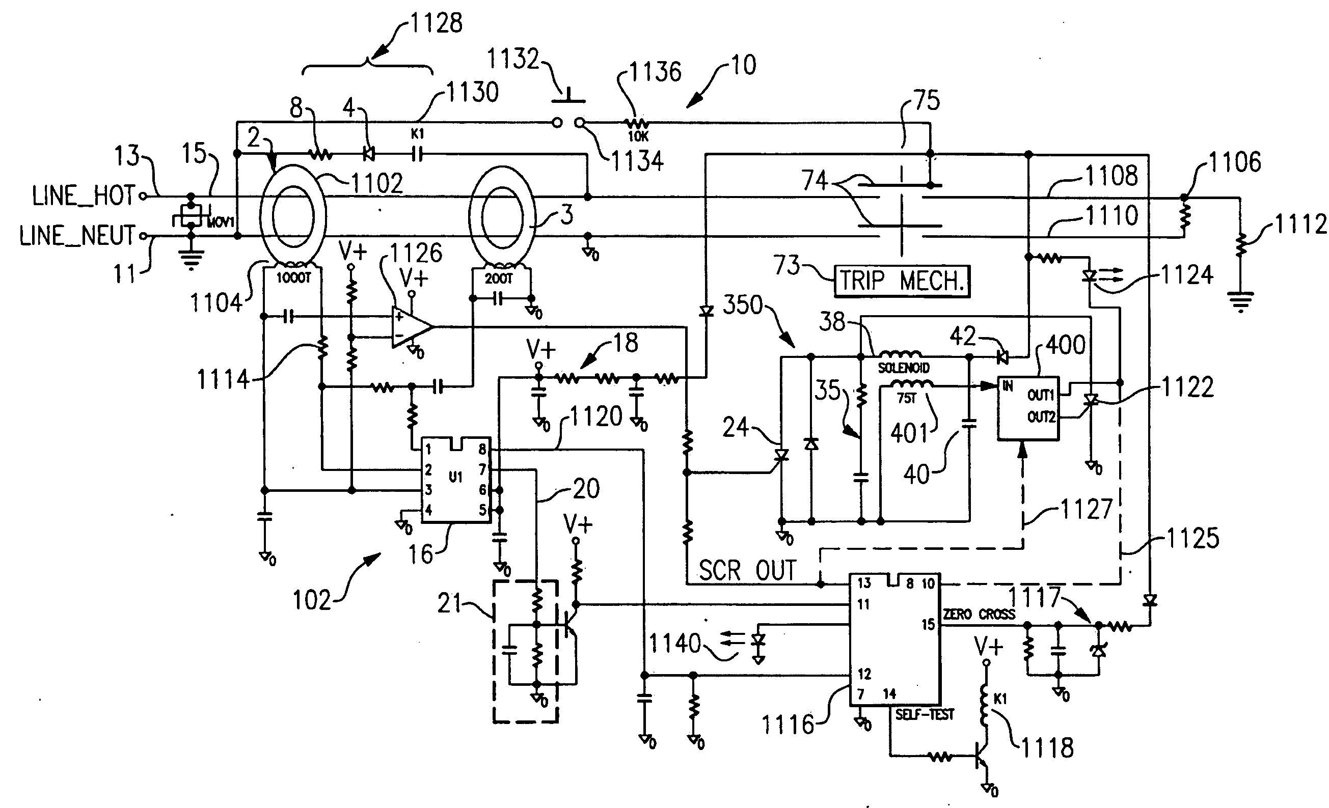
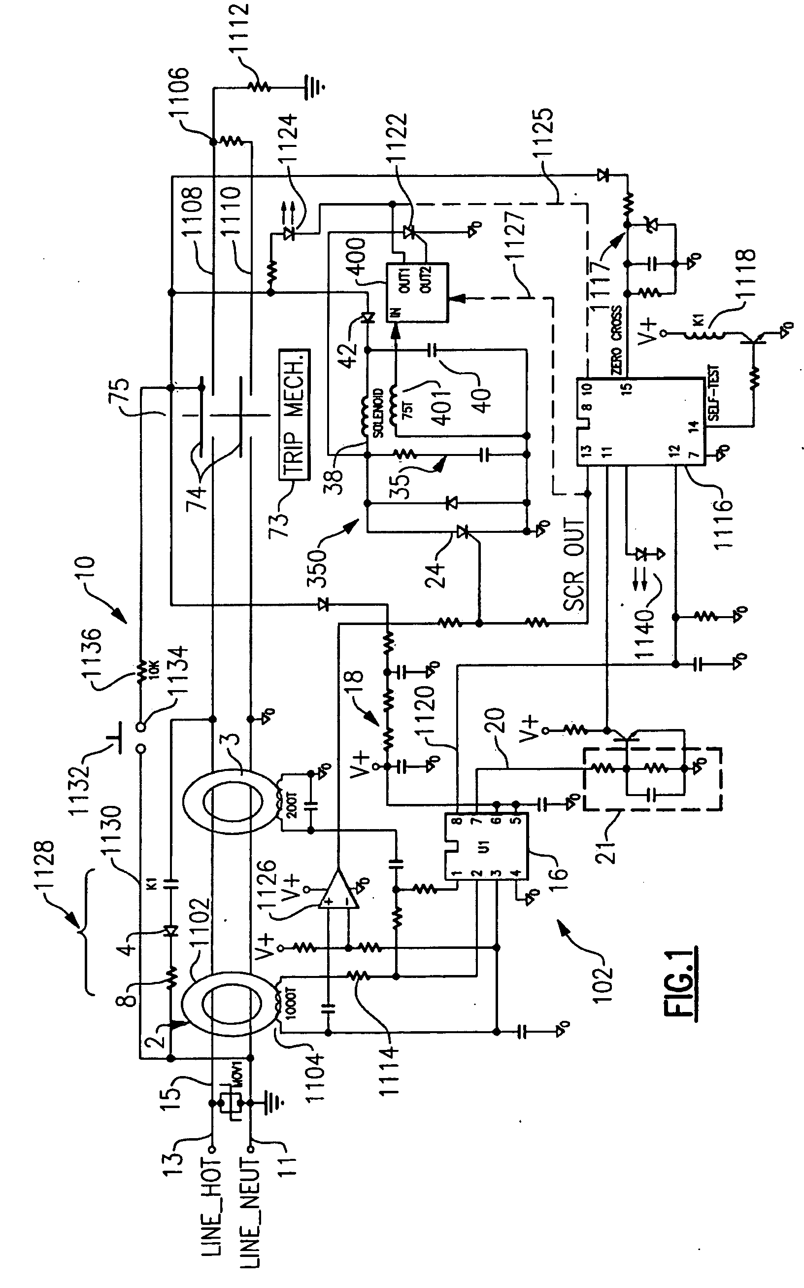
[0081]As embodied herein and depicted in FIG. 9, a schematic of a circuit protection device in accordance with the present invention is disclosed. GFCI 10 includes a GFI circuit 102 and a self test checking circuit 2110. GFI circuit 102 includes a standard GFCI device in which a load-side ground fault is sensed by a differential transformer 2. A transformer 3, which is a grounded neutral transmitter, is used to sense grounded neutral faults. The transformer 2 output is processed by a GFI detector circuit 16 which produces a signal on output 20 that, after filtering in a circuit 21, activates a trip SCR 24. When SCR 24 turns ON, it activates a solenoid 38 which in turn operates a mouse trap device 73, releasing a plurality of contacts 74 and interrupting the load.
[0082]An across-the-line metal oxide varistor (MOV1), also commonly referred to as a movistor, may be included in the protective device such as MOV 15 to prevent damage of the protective device from high voltage surges from ...
PUM
Abstract
The present invention is directed to an electrical wiring device that includes an automatic self-test assembly coupled to the plurality of line terminals or the plurality of load terminals, the detection circuit, the fault detection circuit and the circuit interrupter assembly. The automatic self-test assembly is configured to cause the detection circuit to generate a simulated sensor fault signal during a predetermined half-cycle of an AC line cycle in accordance with a predetermined periodic testing schedule, monitor the fault detection signal corresponding to the simulated sensor fault signal, and generate a test result signal based on monitoring the fault detection signal. The automatic self-test assembly also includes a noise immunized decision circuit configured to evaluate a plurality of test results to thereby provide a noise immunized end-of-life signal. One of the conductive paths that connects the plurality of line terminals and the plurality of load terminals being interrupted in response to the noise immunized end-of-life signal.
Description
CROSS-REFERENCE TO RELATED APPLICATIONS[0001]This is a continuation of U.S. patent application Ser. No. 11 / 025,509 filed on Dec. 29, 2004, which is a continuation-in-part of U.S. patent application Ser. No. 10 / 868,610 filed on Jun. 15, 2004, the contents of which are relied upon and incorporated herein by reference in their entirety, and the benefit of priority under 35 U.S.C. § 120 is hereby claimed.BACKGROUND OF THE INVENTION[0002]1. Field of the Invention[0003]The present invention relates generally to electric circuit protection devices, and particularly to protection devices with an end-of-life indicator.[0004]2. Technical Background[0005]Examples of electric circuit protection devices include ground fault circuit interrupters (GFCIs), arc fault circuit interrupters (AFCIs), or devices that include both GFCIs and AFCIs in one protective device. An electric circuit typically includes at least one protection device. Of course, an electric circuit is configured to transmit AC powe...
Claims
Application Information
Patent Timeline
Application Date:The date an application was filed.
Publication Date:The date a patent or application was officially published.
First Publication Date:The earliest publication date of a patent with the same application number.
Issue Date:Publication date of the patent grant document.
PCT Entry Date:The Entry date of PCT National Phase.
Estimated Expiry Date:The statutory expiry date of a patent right according to the Patent Law, and it is the longest term of protection that the patent right can achieve without the termination of the patent right due to other reasons(Term extension factor has been taken into account ).
Invalid Date:Actual expiry date is based on effective date or publication date of legal transaction data of invalid patent.

