Connector

a technology of connecting rods and connectors, applied in the direction of coupling device details, coupling device connections, electric discharge lamps, etc., can solve the problems of lowering contact reliability, and achieve the effects of small assembly precision, smaller floor area, and larger length dimension of connectors

Active Publication Date: 2009-11-12
ORMON CORP
View PDF1 Cites 18 Cited by
  • Summary
  • Abstract
  • Description
  • Claims
  • Application Information

AI Technical Summary

Benefits of technology

[0009]According to the present invention, retention is realized by mutually engaging the first support fitting and the second support fitting, and thus the length dimension of the connector becomes larger by the plate thickness of the first support fitting. Thus, a connector having a smaller floor area than a related art is obtained.
[0010]As the first support fitting and the second support fitting fixed to the printed circuit boards are directly engaged, the influence due to variation in part precision and assembly precision becomes small. Thus, the variation in the distance between the opposing surfaces of the printed circuit board becomes small, the variation does not arise in the connection state of the socket and the plug, and a connector of high contact reliability is obtained.

Problems solved by technology

As a result, the connection state between the socket 20 and the header 40 tends to vary, thereby lowering the contact reliability.

Method used


Image

  • Connector
  • Connector
  • Connector

Examples


Embodiment Construction

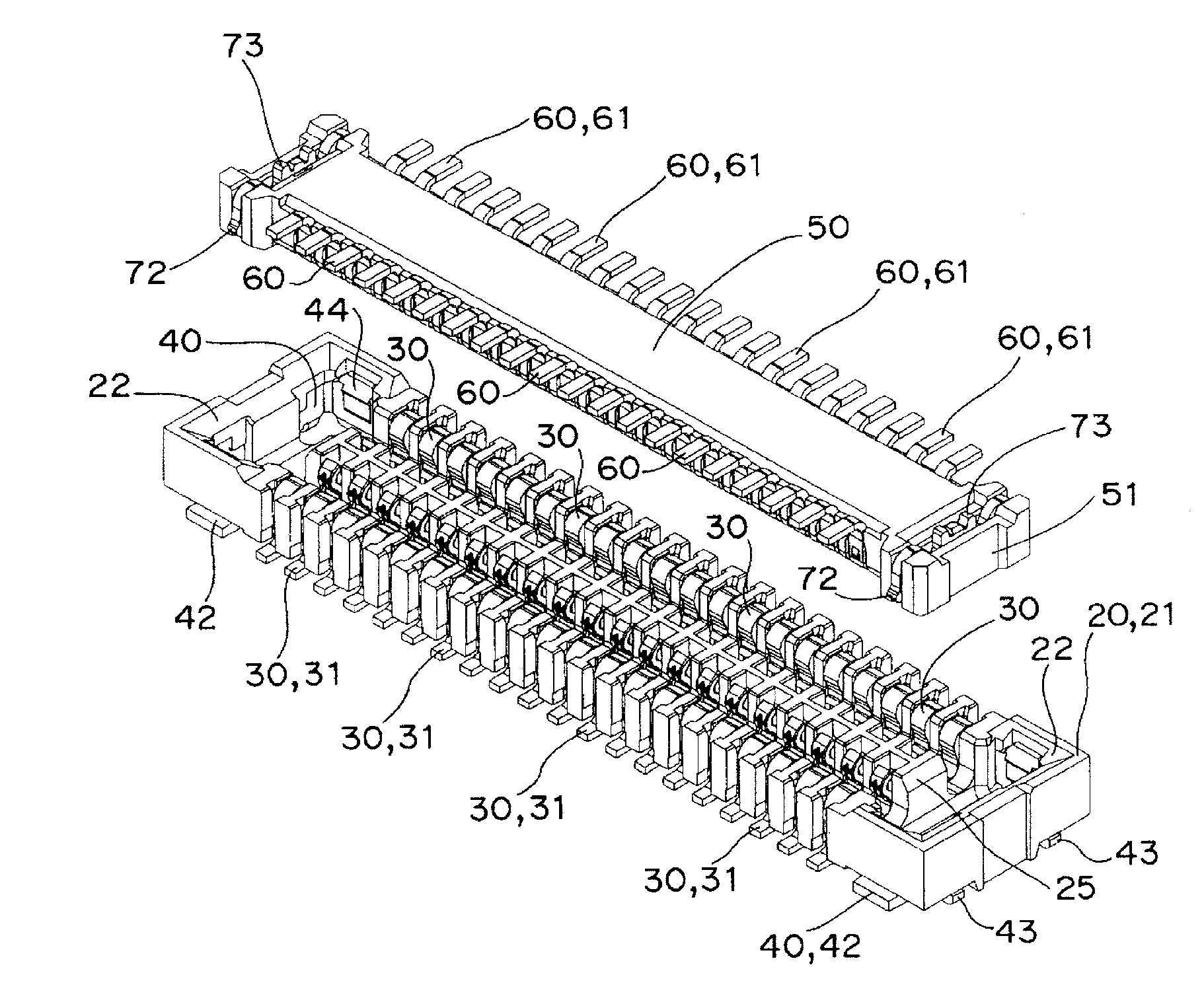
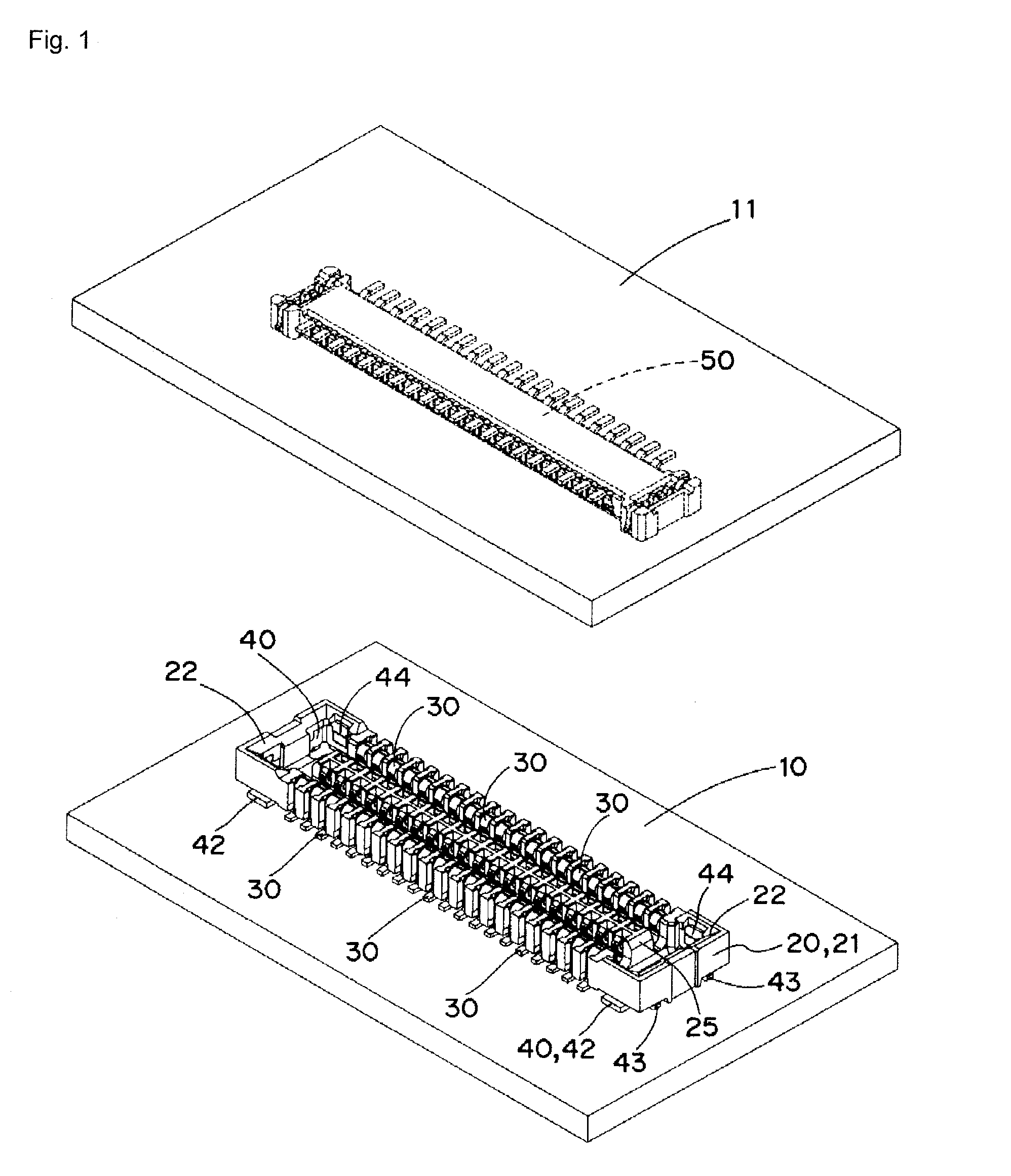
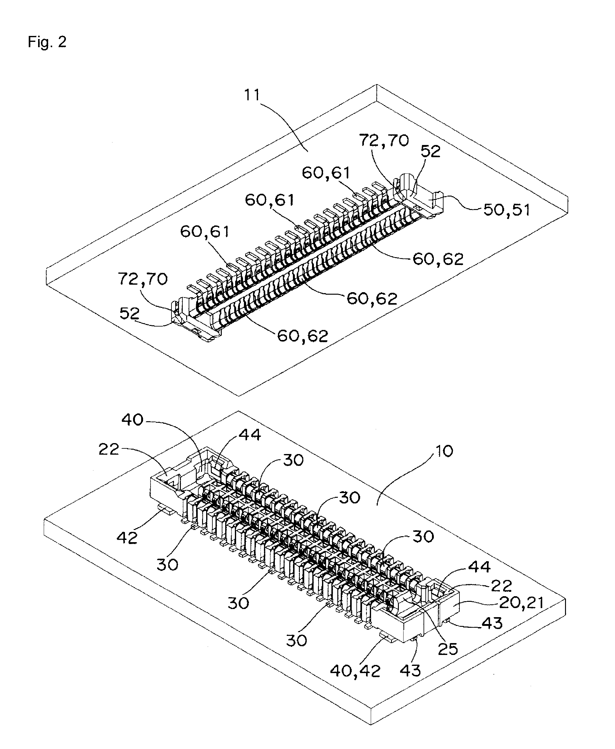
[0039]Hereinafter, preferred embodiments of the connector according to the present invention will be described with reference to the accompanying drawings FIGS. 1 to 18C.

[0040]As shown in FIGS. 1 to 4, the connector according to the present embodiment includes a socket 20 connected to an upper surface of a printed wiring assembly 10, and a plug 50 connected to a lower surface of a printed wiring assembly 11.

[0041]As shown in FIG. 4, the socket 20 is formed by adjacently arranging a plurality of first terminals 30 along the opposing opening edges of a socket main body 21, and assembling a first support fitting 40 to both end edges of the bottom surface.

[0042]As shown in FIGS. 5A to 5C, the socket main body 21 is formed in a box-shape having a shallow bottom, where a guide tapered surface 22 is formed at both end edges of the opening, and a substantially U-shaped press-fit groove 23 for press-fitting the first terminal 30, to be hereinafter described, is adjacently arranged at a prede...


PUM


Abstract

A connector has a plug mounted on a lower surface of a printed circuit board, and a socket mounted on an upper surface of another printed circuit board. The plug is fitted in and electrically connected to the socket. A second support fitting is attached to both ends of a plug main body of the plug and is fixed to the printed circuit board. A first support fitting is attached to both ends of a socket main body of the socket and fixed to the another printed circuit board. The second support fitting is engaged to the first support fitting.

Description

BACKGROUND OF THE INVENTION[0001]1. Technical Field[0002]The present invention relates to connectors, and in particular, to a connector for electrically connecting the opposing printed circuit boards.[0003]2. Related Art[0004]Conventionally, a connector in which a plug mounted on a lower surface of a printed circuit board is fitted into a socket mounted on an upper surface of another printed circuit board to electrically connect the printed circuit boards has been known (see Japanese Unexamined Patent Publication No. 2004-55463).SUMMARY[0005]In the above-described connector, however, a projection 47 of a reinforcement fitting 46 projecting out from a short side of a body 41 of a header 40 serving as a plug is engaged to a lock engagement recessed portion on a body 21 side of a socket 20 for retention. Thus, the entire length of the header 40 becomes long, and consequently, the floor area of the entire connector becomes large.[0006]The reinforcement fitting 46 of the header 40 to be ...

Claims


Application Information

Patent Timeline
Patent Type & Authority Applications(United States)
IPC IPC(8): H01R12/00
CPCH01R13/6275H01R12/707H01R12/716H01R12/7082H01R13/629H01R13/639H01R13/64
Inventor HOSHINO, HIROKAZUSHIMURA, YUSUKE
Owner ORMON CORP
Why Eureka
Try Eureka