Electronic equipment, image forming apparatus, starting method of electronic equipment, and computer program product

Inactive Publication Date: 2009-12-10
RICOH KK
View PDF6 Cites 7 Cited by
  • Summary
  • Abstract
  • Description
  • Claims
  • Application Information

AI Technical Summary

Benefits of technology

[0009]It is an object of the present invention to at least

Problems solved by technology

However, when the hibernation is used in the electronic equipment including the plurality of control unit, and the start methods of all of the control units are not matched, a mismatch of data sent between the control units can occur.
In this case, when another of the control units included in the same electronic equipment is started with the hibernation, the control unit can fail to operate normally at a restart of the control unit.
Because Japanese Patent Application Laid-open No. 2002-207537 does not describe about any application to an electronic equipment including a plurality of control units that start themselves respectively and independently of each other, it is impossible to control the start methods of the control units, individually.
Thus, the operation is inconvenient for the user, and it is difficult to always select the correct start method depending on states of the control unit.

Method used


Image

  • Electronic equipment, image forming apparatus, starting method of electronic equipment, and computer program product
  • Electronic equipment, image forming apparatus, starting method of electronic equipment, and computer program product
  • Electronic equipment, image forming apparatus, starting method of electronic equipment, and computer program product

Examples


first embodiment

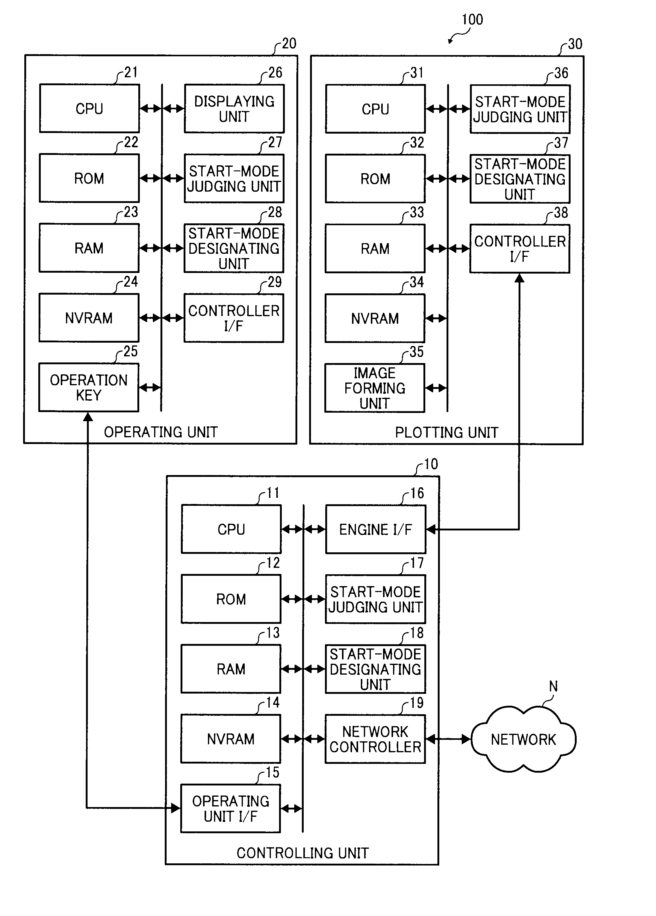
[0023]FIG. 1 is a block diagram of an image forming apparatus 100 according to the present invention. The image forming apparatus 100 includes three control units (functional units): a controlling unit 10, an operating unit 20, and a plotting unit 30.

[0024]The controlling unit 10 integrally manages the operations of the image forming apparatus 100. The controlling unit 10 includes a CPU 11, a ROM 12, a RAM 13, a NVRAM 14, an operating unit interface (I / F) 15, an engine I / F 16, a start-mode judging unit 17, a start-mode designating unit 18, and a network controller 19.

[0025]The CPU 11 controls the operations of the controlling unit 10 integrally in cooperation with predetermined computer programs stored in the ROM 12 and the NVRAM 14. The CPU 11 controls the start and stop of the controlling unit 10. The CPU 11 includes a reset circuit (not shown), and starts the controlling unit 10 based on a reset signal generated by the reset circuit.

[0026]When the controlling unit 10, or the imag...

second embodiment

[0067]FIG. 3 is a block diagram of an image forming apparatus 200 according to the present invention. The image forming apparatus 200 includes three control units: a controlling unit 40, an operating unit 50, and a plotting unit 60.

[0068]The controlling unit 40 integrally manages the operations of the image forming apparatus 200. The controlling unit 40 includes the CPU 11, the ROM 12, the RAM 33, the NVRAM 14, the operating unit I / F 15, the engine I / F 16, a start-mode judging unit 41, a start-mode designating unit 42, and the network controller 19.

[0069]After the controlling unit 40 is started, the start-mode judging unit 41 refers to a start mode set in the NVRAM 14 periodically, and judges whether the start mode is the hibernation start mode or the normal start mode.

[0070]According to control of the CPU 11, the start-mode designating unit 42 sets in the NVRAM 14 the start method instructed by the CPU 11 as the start mode set. When the judgment result by the start-mode judging uni...

third embodiment

[0087]FIG. 5 is a block diagram of an image forming apparatus 300 according to the present invention. The image forming apparatus 300 includes three control units: a controlling unit 70, an operating unit 80, and a plotting unit 90.

[0088]The controlling unit 70 integrally manages the operations of the image forming apparatus 300. The controlling unit 70 includes the CPU 11, the ROM 12, the RAM 33, a NVRAM 71, the operating unit I / F 15, the engine I / F 16, a start-mode judging unit 72, a start-mode designating unit 73, and the network controller 19.

[0089]The NVRAM 71 is a rewritable nonvolatile memory, and stores therein various computer programs and set information to control the controlling unit 70. The NVRAM 71 stores therein the snapshot obtained from the RAM 13 by the CPU 11. The NVRAM 71 stores therein the start modes used when the control unit (the controlling unit 70) and the other control units (the operating unit 80 and the plotting unit 90) are started the next time as the ...


PUM


Abstract

Each of a plurality of control units starts the control unit with one of a first start method and a second start. When a first control unit among the control units starts with a second start method, the first control unit instructs a second control unit among the control units to start with the second start method. Thus, all the control units are started with the same start method.

Description

CROSS-REFERENCE TO RELATED APPLICATIONS[0001]The present application claims priority to and incorporates by reference the entire contents of Japanese priority document 2008-149334 filed in Japan on Jun. 6, 2008.BACKGROUND OF THE INVENTION[0002]1. Field of the Invention[0003]The present invention relates to start controlling of a plurality of control units that can start themselves respectively and independently of each other.[0004]2. Description of the Related Art[0005]Some electronic equipment, such as an image forming apparatus, includes a plurality of functional units. In such electronic equipment, parts that correspond to one function are assembled into a module. Moreover, a control means is provided corresponding to each function to individually control the function. Such a control unit includes a control means (CPUs and the like) whereby the control unit can operate respectively and independently of each other. The control means control starting and stopping of their respectiv...

Claims


Application Information

Patent Timeline
IPC IPC(8): G06F9/445G05B15/00
CPCG06F15/177
InventorKATOH, KATSUHIKO
OwnerRICOH KK