Orthodontic appliance

a technology for orthodontic wires and appliances, applied in the field of orthodontic appliances, can solve the problems of ineffective application of ultrasonic vibration to the teeth to be aligned, easy to give up treatment, and long time-consuming treatment, etc., and achieve the effect of efficient application of vibration and easy and safe continuation

Inactive Publication Date: 2010-03-18
PHC HLDG CORP
View PDF32 Cites 7 Cited by
  • Summary
  • Abstract
  • Description
  • Claims
  • Application Information

AI Technical Summary

Benefits of technology

[0011]The present invention has been worked out to solve the above problems, and has an object to provide an orthodontic appliance which can precisely apply vibration to tooth to be aligned and enables a treatment to be easily and safely continued even at home.
[0013]Since the vibrating element for generating the mechanical vibration (mechanical stimuli) is built in the dental mouthpiece to be mounted on the teeth in this appliance, the vibrating element can efficiently apply the vibration to the tooth to be aligned. Further, the storage of the vibrating element in the dental mouthpiece enables a treatment to be easily and safely continued at any desired time, for example, at home without going to a dental clinic to apply mechanical vibration.

Problems solved by technology

However, the teeth alignment using the orthodontic wire takes a very long time (fastest six months, normally several years) until an orthodontic treatment is finished.
This is likely to become a cause to give up the treatment easily.
However, the appliances disclosed in the above Patent Literatures 1, 2 have a problem that ultrasonic vibration cannot be efficiently applied to the teeth to be aligned since both of them receive the application of ultrasonic vibration from the outside, for example, by pressing an ultrasonic head against the cheek skin.
Further, since the respective appliances require an ultrasonic generator, there is also a problem that treatment cannot be continued unless a patient goes to a dental clinic equipped with these appliances.

Method used


Image

  • Orthodontic appliance
  • Orthodontic appliance
  • Orthodontic appliance

Examples


first embodiment

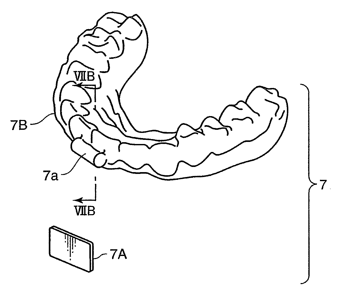
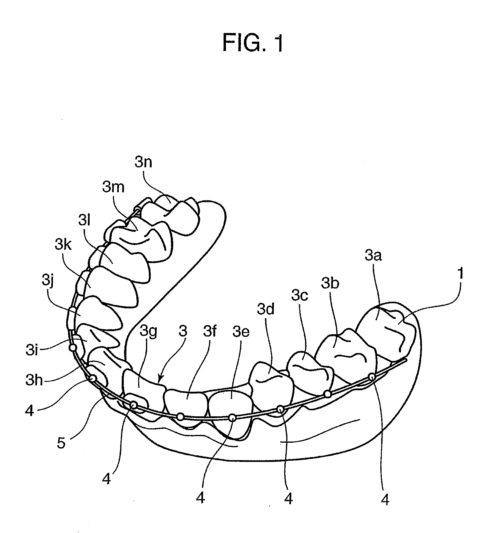
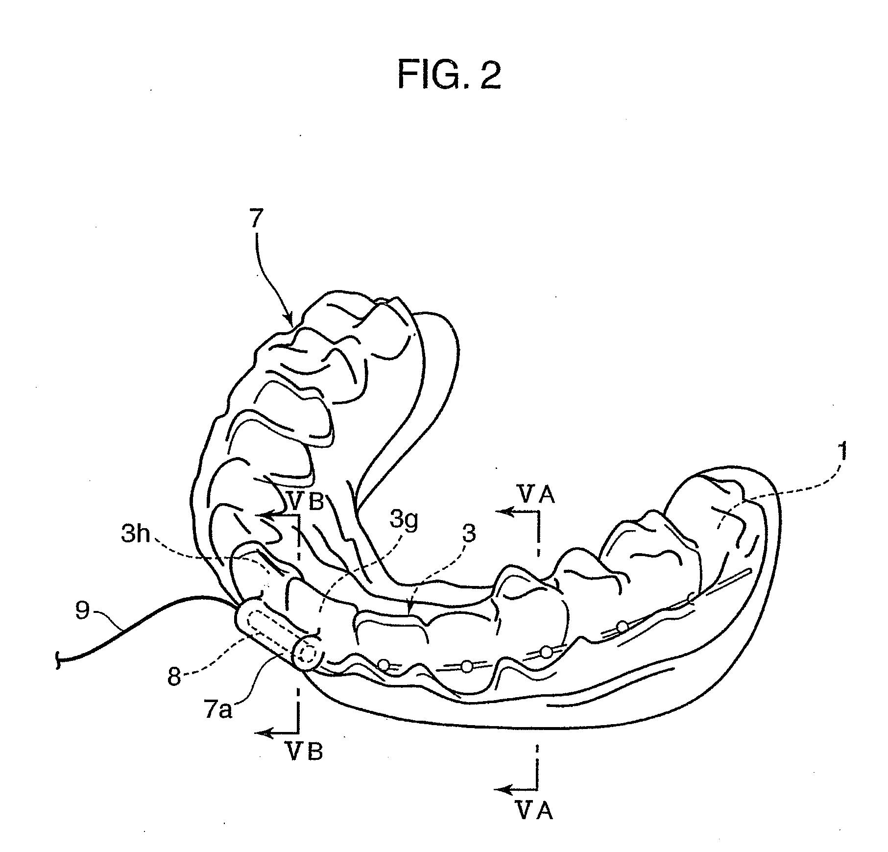
[0059]the present invention is described with reference to FIGS. 1 to 5. FIG. 1 is a perspective view of a dental cast 1 of a lower dental arch according to this embodiment, and FIG. 2 is a perspective view showing a state where a dental mouthpiece 7 according to this embodiment is mounted on teeth 3 of the dental cast 1.

[0060]The teeth 3 shown in FIG. 1 are comprised of teeth 3a to 3n, wherein the teeth 3a, 3n are posterior teeth. Braces are mounted on the teeth 3b to 3m excluding these posterior teeth. These braces include a plurality of brackets 4 to be fixed to the buccal surfaces of the teeth 3b to 3m and an orthodontic wire (arch wire) 5 arranged to connect these brackets 4. This orthodontic wire 5 is latched to the teeth 3b to 3m by the respective brackets 4. The orthodontic wire 5 is elastically deformably latched, so that an elastic restoring force thereof acts as a constant static load on the teeth 3. The application of this static load corrects malocclusion. It should be ...


PUM


Abstract

The present invention concerns an orthodontic appliance for accelerating the tooth aligning effect and shortening the treatment period, and has an object to provide an appliance which can bring about higher aligning effect than usual ways by giving vibration to tooth to be aligned to activate bone remodeling of the targeted tooth and the alveolar bone and enhance the shift of the tooth. This appliance includes a vibrating element and a dental mouthpiece having the vibrating element built therein. The provision of the vibrating element in the dental mouthpiece facilitates the application of vibration and handling, and continues the treatment safely even at home. The inner shape of the dental mouthpiece serves aligning treatment as well as acceleration of the effect.

Description

[0001]The present application is a division of U.S. application Ser. No. 11 / 721,085, filed Jun. 7, 2007, which is a National Stage Application of PCT / JP2007 / 56040, filed Mar. 23, 2007, the disclosures of which incorporated herein by reference in their entireties.TECHNICAL FIELD[0002]The present invention relates to an orthodontic appliance.BACKGROUND ART[0003]An orthodontic appliance equipped with an orthodontic wire to be mounted on teeth has been conventionally known. An elastic restoring force of the orthodontic wire acts as a constant static load on the teeth to correct teeth malalignment or crossbite. In other words, the orthodontic appliance is based on the principle of aligning the teeth by gradually deforming an alveolar bone supporting the teeth through the application of a constant force to the teeth, or bone remodeling.[0004]However, the teeth alignment using the orthodontic wire takes a very long time (fastest six months, normally several years) until an orthodontic trea...

Claims


Application Information

Patent Timeline
Patent Type & Authority Applications(United States)
IPC IPC(8): A61C7/02
CPCA61C7/00A61C7/006A61C13/20A61C7/08A61C7/008A61C7/20
Inventor YAMAMOTOKAMIOKA, HIROSHIADACHI, TAIJIFUKUSHIMA, SHOGOSAKIMURA, TAKUMI
Owner PHC HLDG CORP
Why Eureka
Try Eureka