

System to estimate best time to contact a contact center
a technology of contact center and system, applied in the field of network communication, can solve problems such as long wait times
- Summary
- Abstract
- Description
- Claims
- Application Information
AI Technical Summary
Problems solved by technology
Method used
Image

Examples
Embodiment Construction
General Overview
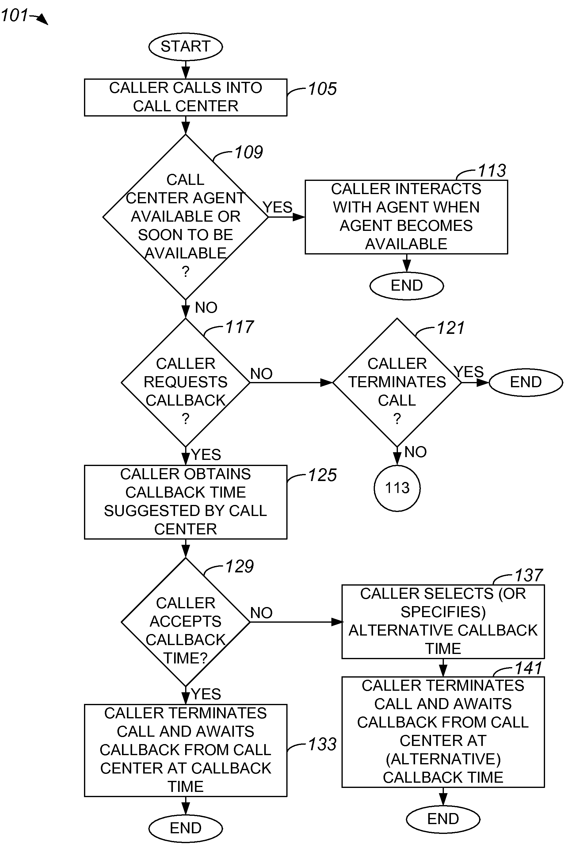
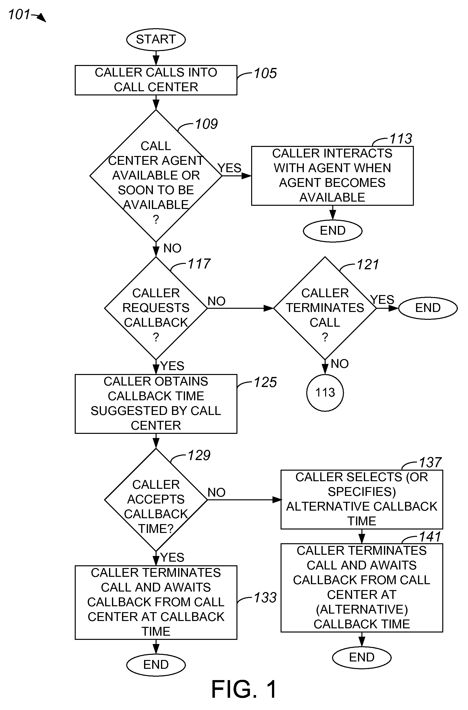
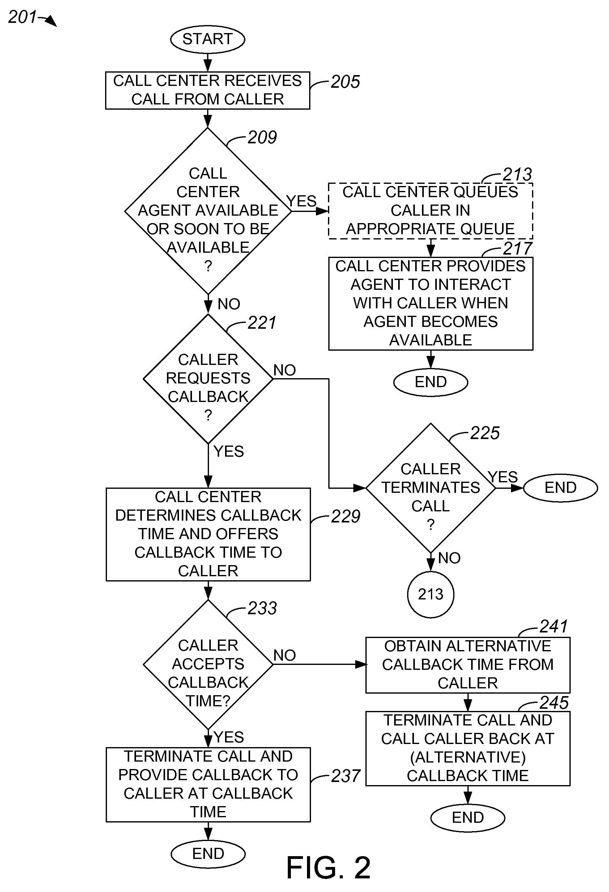
[0009]According to one aspect of the present invention, a method includes obtaining a call from a caller, and determining whether to offer a first callback time to the caller. The first callback time is a future time for a contact between the caller and the call center. The method also includes providing the first callback time to the caller, obtaining a response from the caller, and scheduling the contact at the first callback time if the response indicates that the caller desires a contact at the first callback time. Providing the first callback time to the caller includes soliciting the response from the caller which indicates whether the caller desires the contact at the first callback time.
Description
[0010]A call center system may predict when a call volume into the call center system is likely to be relatively low. If a caller calls into a call center at a time when there are essentially no available agents, e.g., when the call volume into the call center is re...
PUM
 Abstract
Description
Claims
Application Information