Universal joint

a universal joint and joint technology, applied in the direction of yielding coupling, wrenches, screwdrivers, etc., can solve the problems of affecting the torque capacity of the annular collar, the coupling force imparted to the ball will be too high, and the whole articulating adapter will wobbl

Active Publication Date: 2010-07-08
HU BOBBY
View PDF4 Cites 8 Cited by
  • Summary
  • Abstract
  • Description
  • Claims
  • Application Information

AI Technical Summary

Benefits of technology

[0005]The present invention solves this need and other problems in the field of stable and safe operation by providing, in a preferred form, a universal joint including a coupling member having first and second ends spaced along a first axis. The first end of the coupling member is adapted to be coupled to a power drive. A body includes a rounded base and a drive column spaced along a second axis. The rounded base is pivotably mounted to the second end of the coupling member about a pivot axis perpendicular to the first axis, allowing adjustment in an angle between the first and second axes. The body further includes a reinforcing section intermediate the rounded base and the drive column along the second axis. The reinforcing section includes an outer periphery about the second axis. The outer periphery of the reinforcing section includes a recessed portion having a receptacle extending in a radial direction perpendicular to the second axis. The drive column includes a bore extending along the second axis and in communication with the receptacle. The drive column further includes a detent hole extending in a transverse direction transverse to and in communication with the bore. A mover is movably received in the bore along the second axis. A detent member is movably received in the detent hole in the transverse direction. The detent member is operably connected to the mover so that movement of

Problems solved by technology

However, the annular collar is too small to be firmly gripped by the fingers of the operator during tightening or loosening of the fastener, such that the whole articulating adapter wobbles.
If an extra element is added to stabilize the articulating adapter, the extra element would injure the hand of the operator during rotation of the articulating adapter and would adversely affect the torque capacity at the annular collar.
Furthermore, when the spring biasing the ball for securely coupling the socket h

Method used


Image

  • Universal joint
  • Universal joint
  • Universal joint

Examples


Embodiment Construction

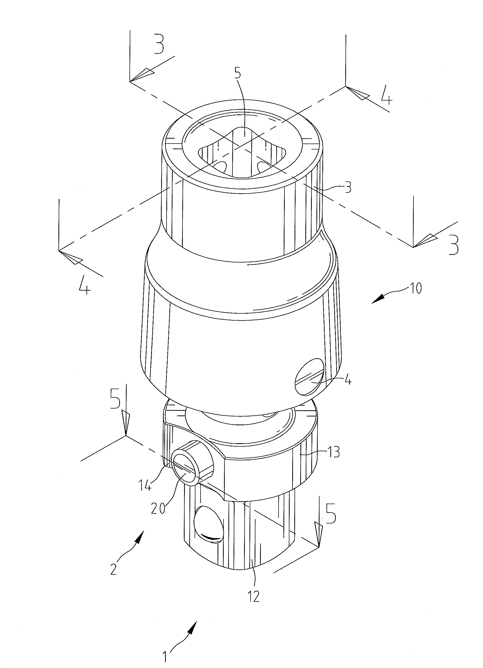
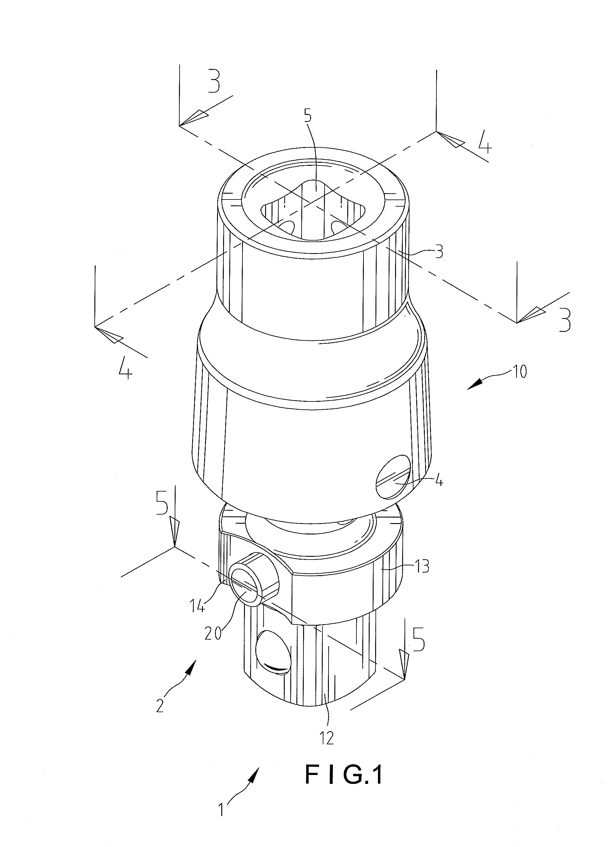
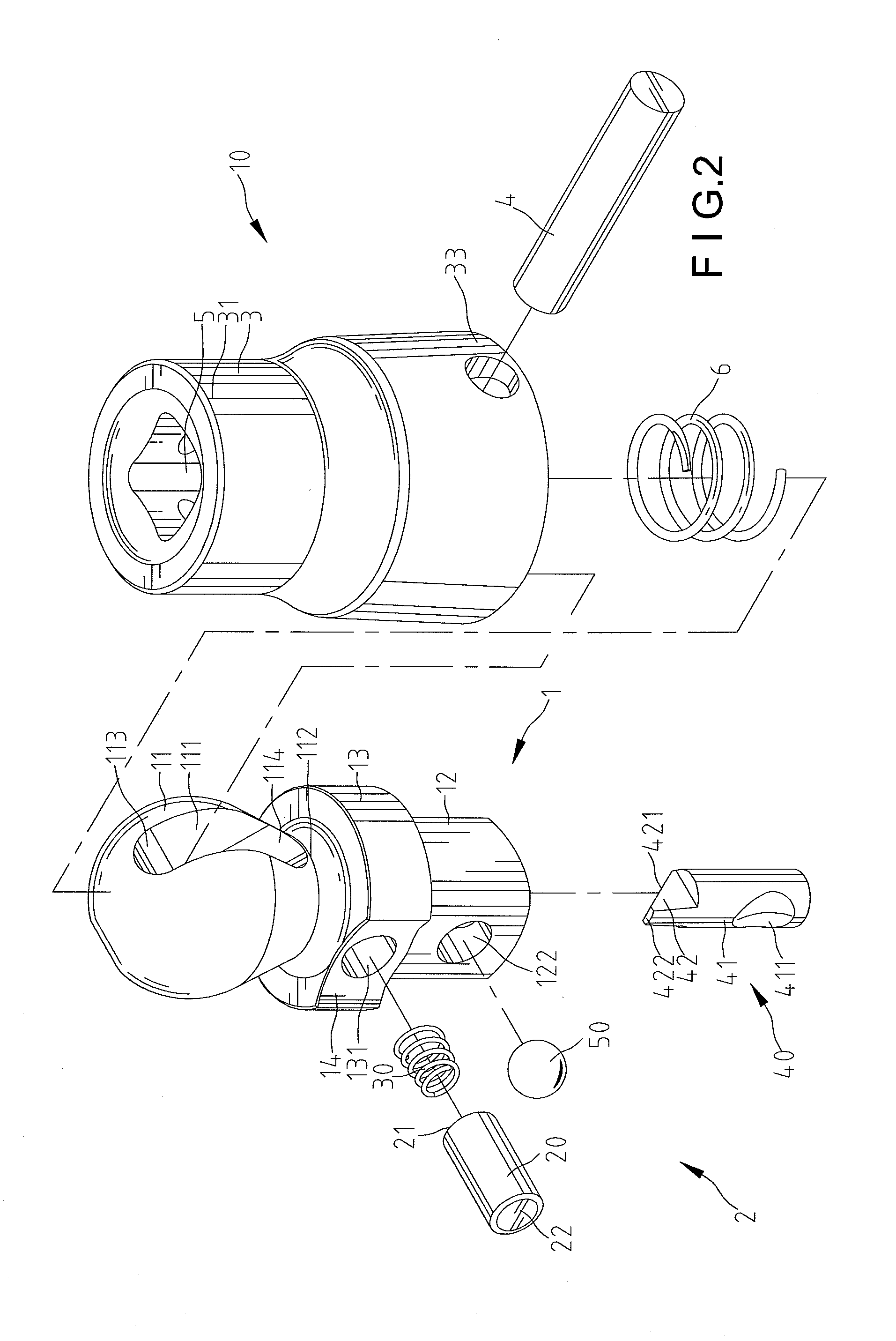
[0021]A universal joint according to the preferred teachings of the present invention is shown in the drawings and generally designated 10. According to the preferred form shown, universal joint 10 includes a body 1, a control device 2, and a coupling member 3. Coupling member 3 includes first and second ends 31 and 33 spaced along a first axis 52. First end 31 of coupling member 3 includes a coupling hole 5 for coupling with a tool including but not limited to a pneumatic or electric tool, so that coupling member 3 can be driven by the tool. Second end 33 of coupling member 3 includes a compartment 32 having an outer section 36 and an inner section 34 intermediate outer section 36 and coupling hole 5 along first axis 52.

[0022]In the preferred form shown, body 1 includes a rounded base 11 and a drive column 12 spaced along a second axis 54. The rounded base 11 is pivotably received in outer section 36 about a pivot axis 56 perpendicular to first axis 52, allowing adjustment in an an...


PUM


Abstract

A universal joint includes a coupling member having an end for coupling with a tool. A body includes a rounded base pivotably mounted to the other end of the coupling member. The body further includes a drive column spaced from the rounded base along an axis. A reinforcing section is intermediate the rounded base and the drive column. The reinforcing section includes an outer periphery having a recessed portion with a receptacle extending in a radial direction perpendicular to the axis. A control member is moveably received in the receptacle to control coupling of the drive column and an object to be driven. In any case, a spacing from an outer end of the control member to the axis in the radial direction is substantially not larger than a spacing from the outer periphery of the reinforcing section to the axis in the radial direction.

Description

BACKGROUND OF THE INVENTION[0001]The present invention relates to a universal joint and, more particularly, to a universal joint including a control member for locking an object such as a socket without the risks of injuring a hand of an operator and avoiding damage to the control member due to impingement by an external object when the universal joint is driven by a power drive.[0002]A typical tool for applying rotational force can be coupled with a socket to rapidly tighten or loosen fasteners in an engine compartment of a vehicle. An extension can be coupled between the tool and the socket to reach a fastener difficult to access. In cases the rotating axis of the fastener is not coincident to the driving axis of the tool, an adaptor such as a universal joint is required.[0003]U.S. Pat. No. 6,092,441 discloses an articulating adapter including first and second drive sections. One of the first and second drive sections is attached to a socket wrench drive while the other is attache...

Claims


Application Information

Patent Timeline
IPC IPC(8): B25B23/16
CPCB25B23/0014B25B23/0035Y10T403/32041F16D3/207
Inventor HU, BOBBY
Owner HU BOBBY
Why Eureka
Try Eureka