Image display device

a technology of image display and display device, which is applied in the direction of lenses, instruments, optical elements, etc., can solve the problems of viewing experience being subjected to physiological effects, and achieve the effect of improving stereoscopic visual effects

Inactive Publication Date: 2010-09-30
ASUKANET
View PDF4 Cites 44 Cited by
  • Summary
  • Abstract
  • Description
  • Claims
  • Application Information

AI Technical Summary

Benefits of technology

[0011]Because an image display device having the two image screens can carry out a display of integr

Problems solved by technology

However, in these systems using the binocular parallax, because a viewer watches a pseudo image as a three-dimensional image of a target

Method used


Image

  • Image display device
  • Image display device
  • Image display device

Examples


first representation embodiment

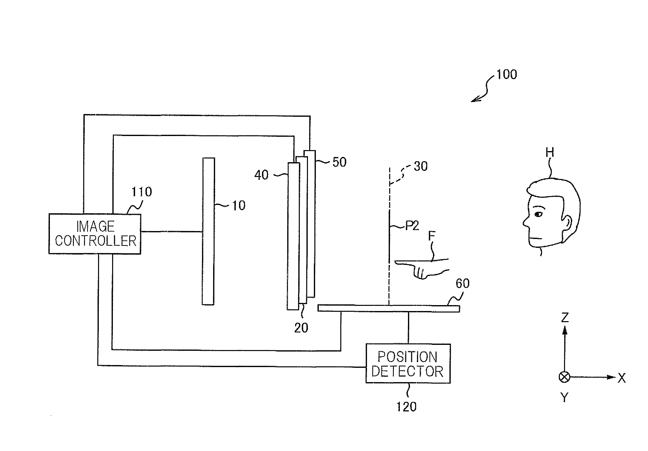
[0100]FIGS. 10 and 11 describe the first representation embodiment of the linking representations of the image display device 100. FIGS. 10 and 11 are views schematically illustrating the first representation embodiment of the linking representations. In the first representation embodiment, the image display device 100 has functions of a car navigation function to be integrated in movable objects, such as motor vehicles. Note that the first representation embodiment assumes that: the running position of a movable object is displayed as a map image, and a menu image of a search target is displayed on the display unit 60. Thus, a search is performed around the current location of the movable object.

[0101]First, when the image display device 100 displays a menu list on the display unit 60 (see (a) of FIG. 10), the viewer (driver) H touches a desired menu in a menu list displayed on the display unit 60 with viewer's finger F (see (b) of FIG. 10). Specifically, the image display device 1...

second representation embodiment

[0109]FIG. 12 describes the second representation embodiment of the linking representations of the image display device 100. FIG. 12 is a view schematically illustrating the second representation embodiment of the linking representations. In the second representation embodiment, the image display device 100 has functions of a car navigation function to be integrated in movable objects, such as motor vehicles. Note that the second representation embodiment assumes that: the running position of a movable object is displayed on the display unit 40 on the display unit 40 as a map image, and information indicative of traffic jam is provided.

[0110]First, when a communication device of the movable object receives the information indicative of traffic congestion, the image display device 100 displays, as the floating image P2, a 3D icon indicative of “occurrence of traffic jam” as a popup and displays a warning message on the display unit 60 (see (a) of FIG. 12 corresponding to step S10 in ...

third representation embodiment

[0123]FIGS. 13 and 14 describe the third representation embodiment of the linking representations of the image display device 100. FIGS. 13 and 14 are views schematically illustrating the third representation embodiment of the linking representations. In the third representation embodiment, the image display device 100 has functions of a music playback system. Note that the third representation embodiment assumes that: a title menu of albums, such as CD and records, and music of a selected album by a viewer (an audience) is played.

[0124]First, when the image display device 100 displays the title menu on the image screen 61 of the display unit 60 (see (a) of FIG. 13), the viewer H operates a scroll bar to thereby search, while scrolling the title menu, for an album to be played in the title menu (see (b) of FIG. 13). When finding an album to be played, the viewer H touches the title of the album to be played with a finger F (see (c) of FIG. 13); this title of the album to be played i...


PUM


Abstract

An image display device 100 includes: a display unit 10 having an image screen 11 for displaying a two-dimensional image; an image transfer panel 20 located on a path of light left from the image screen 11; a floating image display unit 1 that displays, as a floating image, the light left from the image screen 11 in a space located on one side of the image transfer panel 20 opposite to the other side thereof facing the display unit 10; a direct-view image display unit 2 provided with a display unit 40 having an image screen 41 for displaying a two-dimensional image displayed on the image screen 41 as a direct view image. The image display device carries out:
    • floating-image control that displays the floating image P2 such that the given object displayed as the floating image P2 is shifted in a specified first direction from the displayed position of the floating image P2 to the image screen 41; and
    • direct-view image control that executes a process associated with the given object during or after the shift of the given object, and displays, on the image screen 41, a two-dimensional image on which the executed process is reflected.

Description

TECHNICAL FIELD OF THE INVENTION[0001]The present invention relates to image display devices for pseudo-stereoscopically displaying two-dimensional images.BACKGROUND ART[0002]Recently, various systems for providing viewers stereoscopic images are proposed.[0003]In these types of image display devices, there are common systems that use binocular parallax to thereby provide, as three-dimensional images, two-dimensional images on an image screen of a display or the like.[0004]However, in these systems using the binocular parallax, because a viewer watches a pseudo image as a three-dimensional image of a target object, the focus on the image screen and the convergence are off from each other, the viewer may be subjected to physiological effect.[0005]Thus, as another system, an image display device, in which an image transfer panel (for example, a microlens array consisting of a plurality of lenses) is placed in front of a two-dimensional image at a predetermined space therefrom, for dis...

Claims


Application Information

Patent Timeline
IPC IPC(8): G06T15/00G06F3/041H04N13/388
CPCG02B3/0062H04N13/0493G06F3/041G02B27/2292H04N13/393G02B30/56G06F3/0488H04N13/388
Inventor TOMISAWA, ISAOISHIKAWA, MASARUTAKAHASHI, TAKEHIRO
Owner ASUKANET
Why Eureka
Try Eureka