Imaging device, image processing method and program

a technology of image processing and imaging device, applied in the direction of instruments, television systems, carrier indicating arrangements, etc., can solve the problems of affecting the quality of the image, the inability to check the content of the recorded moving image, and the inability to edit the moving image etc., etc., and the time taken to perform the next recording may be missed

Active Publication Date: 2010-12-09
SONY CORP
View PDF2 Cites 44 Cited by
  • Summary
  • Abstract
  • Description
  • Claims
  • Application Information

AI Technical Summary

Benefits of technology

[0022]According to the embodiments of the present invention described above, the content of the recorded moving images

Problems solved by technology

Furthermore, when the recording time is long, auto review immediately after moving image pickup takes a long time, and a timing to perform the next recording may be missed.
In contrast, with moving images, there is the concept of recording time, and thus, if time elapses from the time of image pickup, o

Method used


Image

  • Imaging device, image processing method and program
  • Imaging device, image processing method and program
  • Imaging device, image processing method and program

Examples


first embodiment

1. First Embodiment

[0048]Structure of Imaging Device

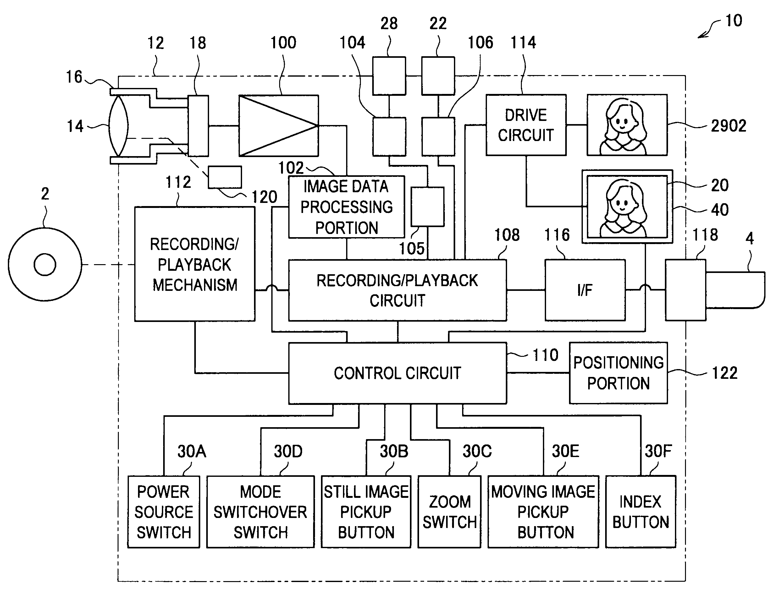
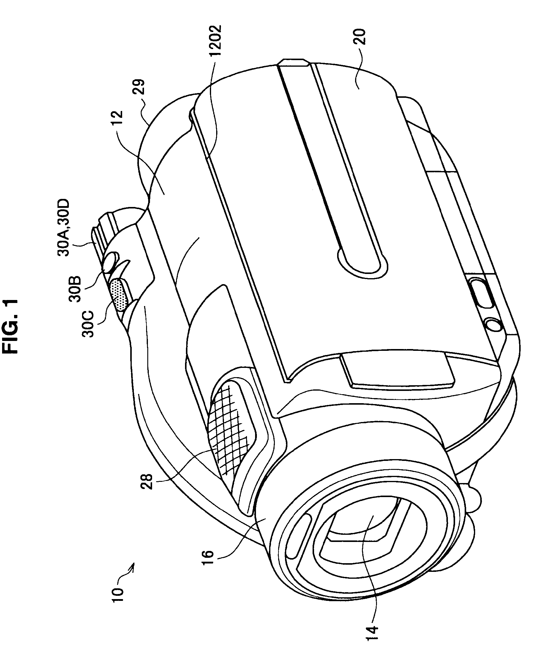
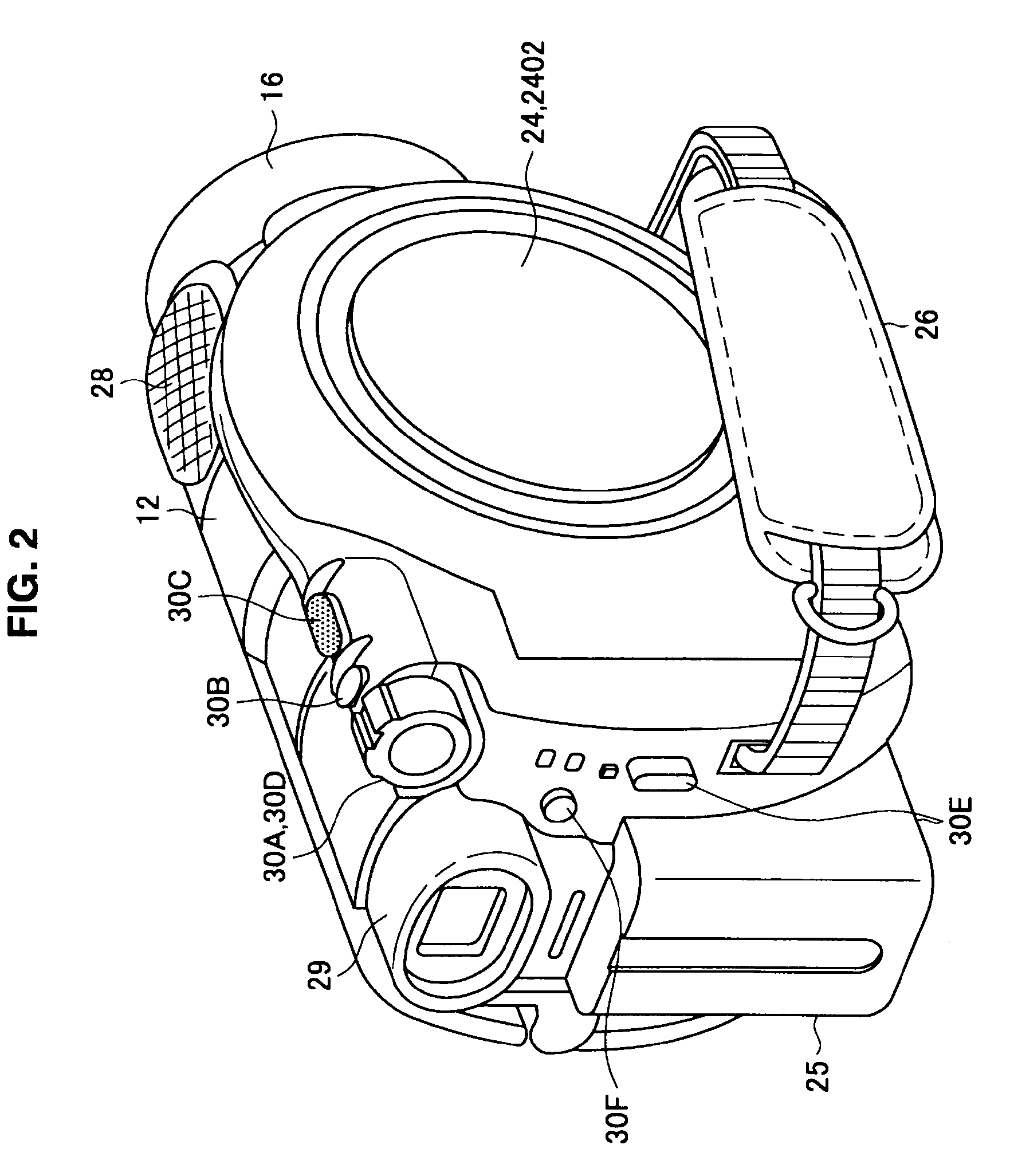
[0049]First, a structure of an imaging device according to a first embodiment of the present invention will be explained with reference to FIG. 1 to FIG. 3. FIG. 1 and FIG. 2 are perspective views showing an external structure of a front surface side and a rear surface side of an imaging device 10 according to the first embodiment. FIG. 3 is a block diagram showing a hardware configuration of the imaging device 10 according to the first embodiment.

[0050]As shown in FIG. 1 and FIG. 2, the imaging device 10 according to the first embodiment is, for example, a digital video camera, and has functions to capture and record moving images. However, the imaging device according to the present invention is not limited to the example of the digital video camera and can also be applied to any chosen electronic device, as long as it is capable of recording moving images where a photographic subject is continuously captured. It can be, for exam...

second embodiment

2. Second Embodiment

[0155]Next, a second embodiment of the present invention will be described. Immediately after the recording of the moving images, in addition to the recorded image verification screen 300 according to the first embodiment described above, the imaging device 10 according to the second embodiment displays a map screen 400. Note that, in the second embodiment, in comparison with the first embodiment, the point of difference is the display of the map screen 400, and the rest of the functional structure is substantially the same as in the first embodiment. A detailed explanation is thus omitted here.

[0156]Examples of display of recorded image verification screen and map screen Examples of display of the recorded image verification screen 300 and the map screen 400 according to the second embodiment will be explained with reference to FIG. 8 and FIG. 9. FIG. 8 is a diagram showing an example of display of the recorded image verification screen 300 according to the pres...

third embodiment

3. Third Embodiment

[0170]Next, a third embodiment of the present invention will be described. The imaging device 10 according to the third embodiment displays thumbnail images 510 on a recorded image verification screen 500 in a display format that depends on the time length of the section corresponding to each of the thumbnail images 510. Note that in the third embodiment, the display format of the thumbnail images 510 is different to that of the first embodiment, but the rest of the functional structure is substantially the same as in the first embodiment. A detailed explanation is thus omitted here.

[0171]Example of Display of Recorded Image Verification Screen

[0172]First, an example of display of the recorded image verification screen 500 according to the third embodiment will be explained with reference to FIG. 11 to FIG. 13. FIG. 11 to FIG. 13 are diagrams showing examples of display of the recording image verification screen 500 according to the present embodiment. FIG. 11 is ...


PUM


Abstract

There is provided an imaging device including, an operating portion on which are input a recording start instruction and a recording stop instruction, a recording portion that records onto a recording medium moving images that are picked up during a recording period from the recording start instruction to the recording stop instruction, a thumbnail generation portion that generates a plurality of thumbnail images that represent each of sections obtained by time division of the moving images, and a display control portion that displays a recorded image verification screen on a display portion immediately after the recording stop instruction, the plurality of thumbnail images being arranged in chronological order on the recorded image verification screen.

Description

BACKGROUND OF THE INVENTIONField of the Invention[0001]The present invention relates to an imaging device, an image processing method and a program.[0002]2. Description of the Related Art[0003]When performing pickup of still images (photographs, for example) on an imaging device such as a digital still camera or the like, immediately after a still image is taken and recorded in response to depression of a shutter button, the recorded still image is automatically displayed for a predetermined period of time only (auto review) and after that period of time an operation generally moves to an image pickup standby state (as disclosed, for example, in Japanese Patent Application Publication No. JP-A-2005-340904). Using this type of auto review function, a user can verify content of the recorded still image immediately after image pickup without performing any particular operation. For that reason, when the user decides that the image pickup is unsuccessful, the user can delete the recorde...

Claims


Application Information

Patent Timeline
IPC IPC(8): H04N5/91
CPCG11B27/34H04N1/00411H04N1/00453H04N5/772H04N1/2112H04N5/23216H04N5/23293H04N1/00474H04N23/62H04N23/632
Inventor IWASE, AYAKOSAITOU, YUJINUNOMAKI, TAKASHIFURUE, NOBUKIIRIYA, SHINICHIOZAWA, HIROYUKI
Owner SONY CORP
Why Eureka
Try Eureka