Circuit for controlling a lighting unit with light-emitting diodes

a technology of light-emitting diodes and circuits, which is applied in the direction of electric variable regulation, process and machine control, instruments, etc., can solve the problems of increasing the lifetime of supply modes, reducing the cost of high-voltage capacitors, and reducing the life of diodes

Inactive Publication Date: 2010-12-16
STMICROELECTRONICS (TOURS) SAS
View PDF5 Cites 2 Cited by
  • Summary
  • Abstract
  • Description
  • Claims
  • Application Information

AI Technical Summary

Benefits of technology

[0008]An object of an embodiment of the present invention is to provide such a circuit improving the lifetime of the diodes.
[0009]An object of an embodiment of the present invention is to provide such a circuit which has low cost and is easy to form.

Problems solved by technology

Such diodes especially have a long lifetime and a high light output.
This power supply mode has the disadvantage of decreasing their lifetime.
Further, linear power supply circuits generally comprise high-voltage capacitors having the disadvantage of being expensive and bulky.

Method used


Image

  • Circuit for controlling a lighting unit with light-emitting diodes
  • Circuit for controlling a lighting unit with light-emitting diodes
  • Circuit for controlling a lighting unit with light-emitting diodes

Examples


Embodiment Construction

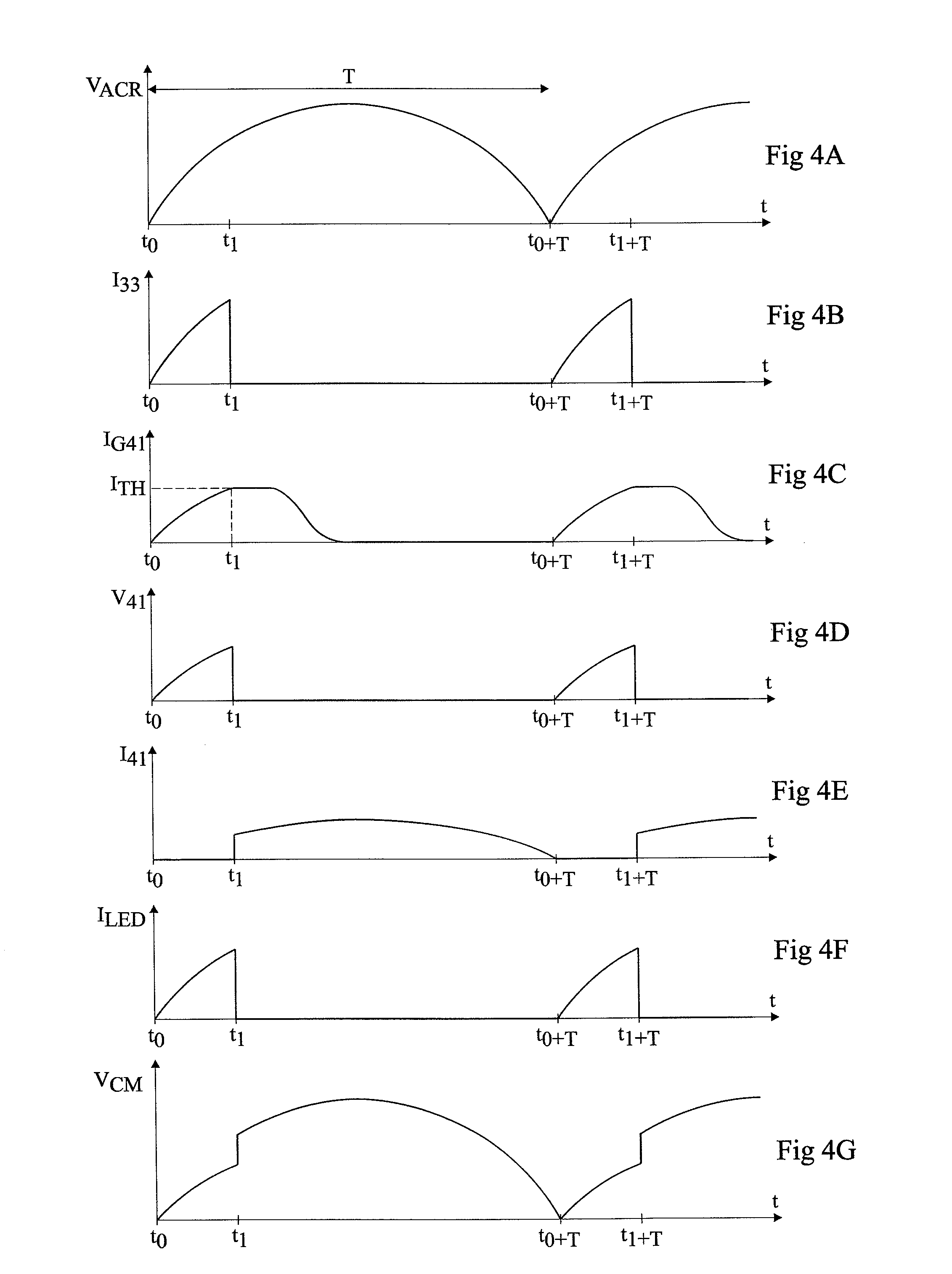
[0025]For clarity, the same elements have been designated with the same reference numerals in the different drawings. Further, the timing diagrams of FIGS. 4A to 4G are not to scale.

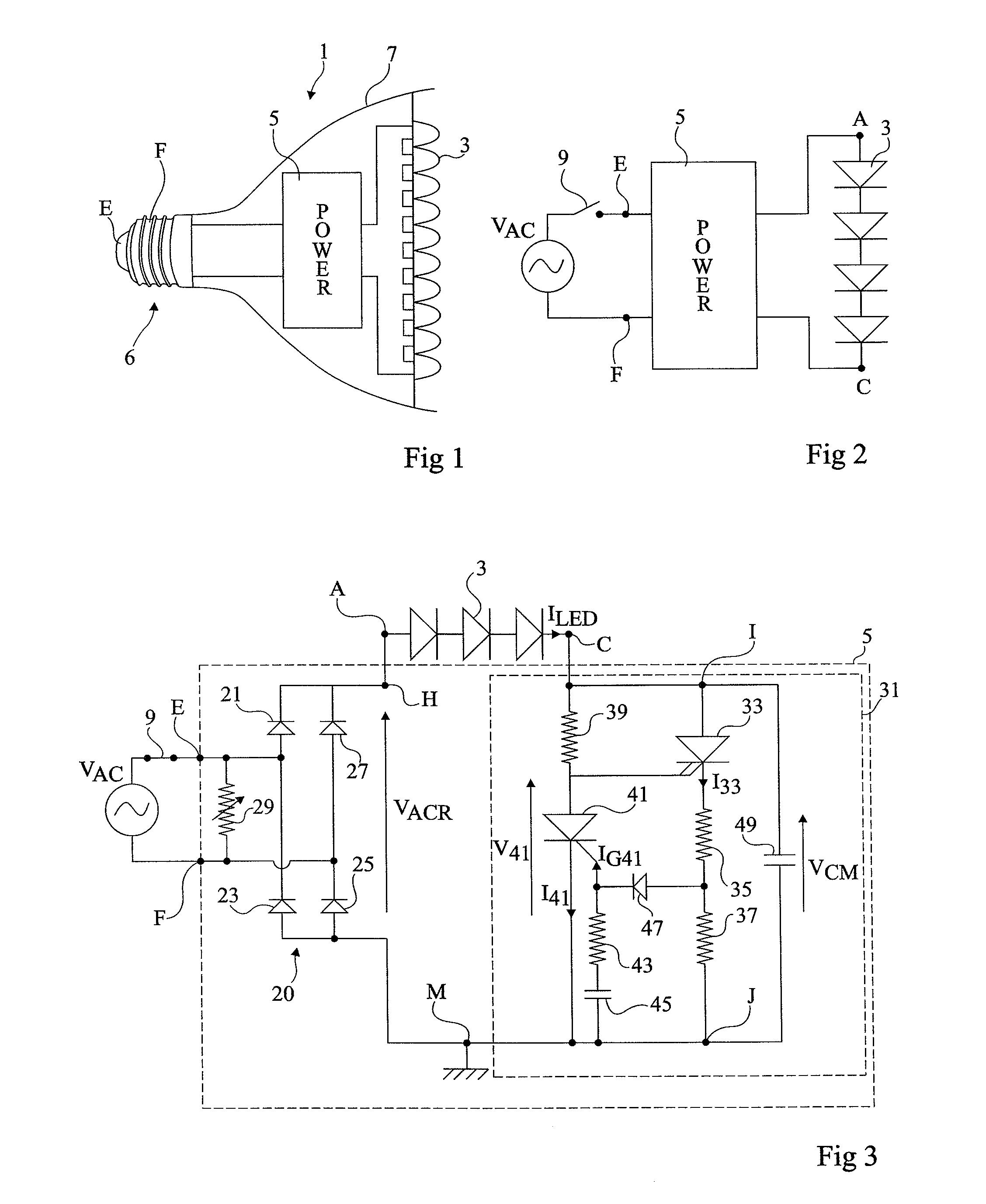
[0026]FIG. 1 is a simplified view of an illumination device 1 with light-emitting diodes 3.

[0027]FIG. 2 is a simplified electric diagram of device 1.

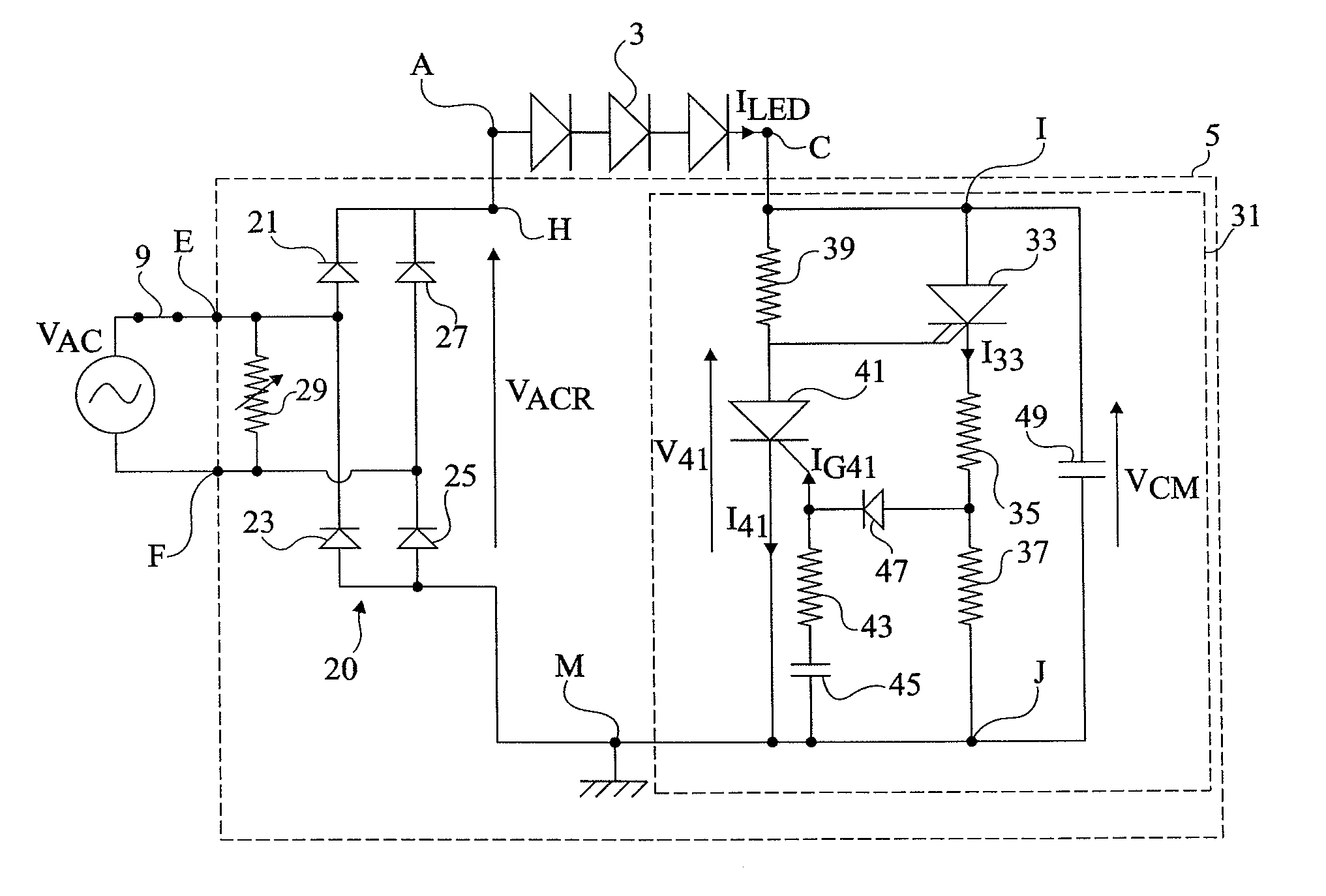
[0028]Device 1 comprises an assembly of light-emitting diodes 3 in series. Terminals A and C (FIG. 2) of diode assembly 3 are connected to a power supply circuit 5 (POWER). In the shown example, terminals A and C respectively correspond to the anode and cathode connection terminals of the assembly of diodes 3 in series.

[0029]Circuit 5 is capable of receiving an A.C. voltage VAC (FIG. 2), for example, the mains voltage, and of providing a power adapted to the electrical characteristics of the assembly of diodes 3. Input terminals of power supply circuit 5 are connected to terminals E and F of a base 6. Base 6 may have any shape adapted to a connection on a so...


PUM


Abstract

A circuit capable of receiving, in series with at least one light-emitting diode, a rectified A.C. voltage, comprising: a first gate turn-off thyristor connected to first and second terminals of the circuit; and a control circuit for turning off the first thyristor when the voltage between the first and second terminals exceeds a threshold.

Description

CROSS REFERENCE TO RELATED APPLICATIONS[0001]This application claims the priority benefit of French patent application number 09 / 53922, filed on Jun. 12, 2009, entitled “CIRCUIT FOR CONTROLLING A LIGHTING UNIT WITH LIGHT-EMITTING DIODES,” which is hereby incorporated by reference to the maximum extent allowable by law.BACKGROUND OF THE INVENTION[0002]1. Field of the Invention[0003]The present invention relates to lighting units with light-emitting diodes intended to receive an A.C. supply voltage. It more specifically relates to circuits for powering such devices.[0004]2. Discussion of the Related Art[0005]For a long time, illumination devices have been formed based on incandescent light bulbs or on fluorescent tubes capable of receiving an A.C. supply voltage, for example, a 220-V mains voltage at 50 Hz. More recently, it has been desired to use light-emitting diodes. Such diodes especially have a long lifetime and a high light output. They however require a power supply circuit ca...

Claims


Application Information

Patent Timeline
Patent Type & Authority Applications(United States)
IPC IPC(8): H05B37/02H05B44/00
CPCH05B33/0815H05B39/044Y02B20/19Y02B20/348H05B33/0818Y02B20/00Y02B20/30H05B45/31
Inventor GONTHIER, LAURENTPASSAL, ANTOINE
Owner STMICROELECTRONICS (TOURS) SAS
Why Eureka
Try Eureka