Focus control circuit for adjusting the focus by moving a lens

a control circuit and lens technology, applied in the direction of camera focusing arrangement, printers, instruments, etc., can solve the problem of taking a long time to complete a search, and achieve the effect of less cost and maximum contrast of a subj

Active Publication Date: 2011-01-20
SEMICON COMPONENTS IND LLC
View PDF9 Cites 4 Cited by
  • Summary
  • Abstract
  • Description
  • Claims
  • Application Information

AI Technical Summary

Benefits of technology

[0006]The contrast detecting method can be achieved with less cost than an active method in which the subject is irradiated with infrared rays or ultrasonic waves and the distance to the subject is measured based on the reflected waves. Nevertheless, the contrast method has a drawback in that it takes some time to complete a search for the lens position in which the contrast of a subject is maximized. It is desired that the processing of focusing the subject be completed within one second after a user has pressed a shutter button halfway.
[0007]The number of pixels of each cameral module installed in the commonly-used digital cameras and mobile phones is increasing every year. As a result, high-resolution images can be easily taken with such a compact-size camera. When the high-resolution images are taken, out-of-focus shots may be easily noticeable and therefore further high-precision auto-focus control is required.

Problems solved by technology

Nevertheless, the contrast method has a drawback in that it takes some time to complete a search for the lens position in which the contrast of a subject is maximized.

Method used


Image

  • Focus control circuit for adjusting the focus by moving a lens
  • Focus control circuit for adjusting the focus by moving a lens
  • Focus control circuit for adjusting the focus by moving a lens

Examples


Embodiment Construction

[0015]The invention will now be described by reference to the preferred embodiments. This does not intend to limit the scope of the present invention, but to exemplify the invention.

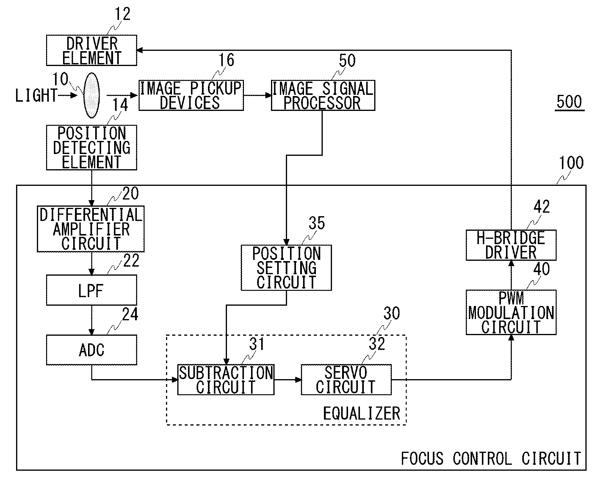
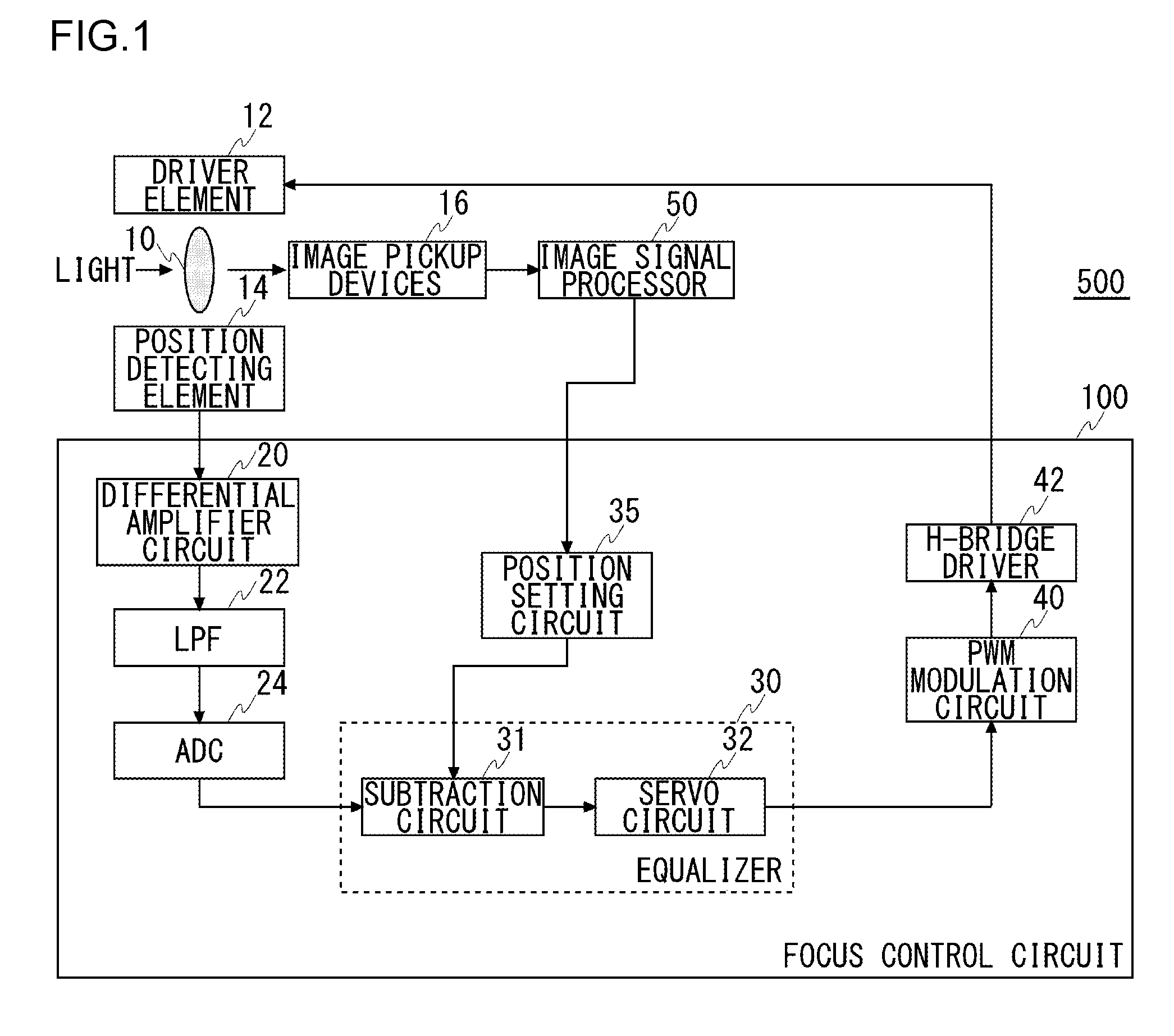
[0016]FIG. 1 illustrates a structure of an image pickup apparatus 500 provided with a focus control circuit 100 according to an embodiment of the present invention. The image pickup apparatus 500 includes a lens 10, a driver element 12, a position detecting element 14, image pickup devices 16, an image signal processor (ISP) 50, and a focus control circuit 100. Other structural components, such as an image coding engine and a recording medium, which are not involved in the auto-focus control are omitted in FIG. 1.

[0017]The image pickup devices 16 convert the light signals transmitted through the lens 10, which is an optical component, into electric signals and outputs the electric signals to the image signal processor 50. The image pickup devices 16 may be CCD (charge-coupled device) sensors or CMOS (com...


PUM


Abstract

A focus control circuit is installed in an image pickup apparatus including a lens, a driver element for adjusting the position of the lens, and a position detecting element for detecting the position of the lens. An equalizer included in the focus control circuit generates a drive signal used to adjust the position of the lens to a position to be set, based on a difference between the position of the lens identified by the position detecting element and the set position. When an instruction to vary a target position of the lens is received externally, a position setting unit included in the focus control circuit sets sequentially a plurality of positions in a range covering a new target position and a previous target position, to the equalizer before the new target position is reached from the previous target position.

Description

CROSS-REFERENCE TO RELATED APPLICATIONS[0001]This application is based upon and claims the benefit of priority from the prior Japanese Patent Applications No. 2009-167113, filed on Jul. 15, 2009, and Japanese Patent Application No. 2010-127584, filed on Jun. 3, 2010, the entire contents of which are incorporated herein by referenceBACKGROUND OF THE INVENTION[0002]1. Field of the Invention[0003]The present invention relates to a focus control circuit for determining the focus position by actively moving a lens.[0004]2. Description of the Related Art[0005]Most of camera modules installed in commonly-used digital cameras and mobile phones are provided with auto-focusing functions. A contrast detecting method is often used as the auto-focusing function employed in such a compact-size camera. In the contrast detecting method, a lens position in which the contrast of a subject lying in a picked-up image frame is maximized is detected by actively moving the lens and then the lens is moved ...

Claims


Application Information

Patent Timeline
Patent Type & Authority Applications(United States)
IPC IPC(8): G03B13/34
CPCG03B13/34
Inventor NAGAI, HIROKIKURA, TAKESHIKAMIYA, TOMONORI
Owner SEMICON COMPONENTS IND LLC
Why Eureka
Try Eureka