

Transmit diversity method applied to a transmitting system and transmitting system having multi-transmission paths thereof
- Summary
- Abstract
- Description
- Claims
- Application Information
AI Technical Summary
Problems solved by technology
Method used
Image



Examples
first embodiment
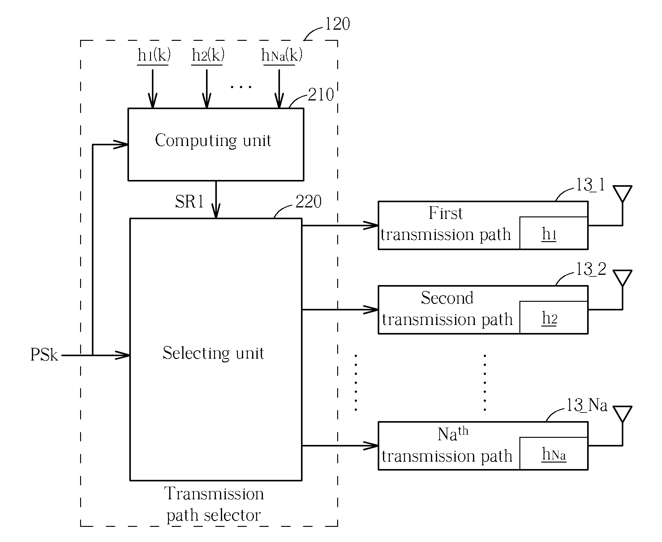
[0022]Please refer to FIG. 1. FIG. 1 is a block diagram of a transmitting system 100 having multi-transmission paths according to the present invention. As FIG. 1 depicts, the transmitting system 100 includes, but is not limited to, a serial-to-parallel transform circuit 110, a transmission path selector 120, and at least two transmission paths 13_1˜13_Na. The serial-to-parallel transform circuit 110 receives a serial stream SS1, and transforms the serial stream SS1 into a plurality of parallel streams PS1˜PSN, wherein each parallel stream PS1˜PSN is carried by a corresponding sub-carrier. In this embodiment, totally N parallel streams PS1˜PSN are cited as an example for illustrating the present invention, that is to say, totally N sub-carriers SC1˜SCN are required to carry the N parallel streams PS1˜PSN. Moreover, the transmission path selector 120 is coupled between the serial-to-parallel transform circuit 110 and these transmission paths 13_1˜13_Na. In light of each sub-carrier (...
second embodiment
[0031]Please refer to FIG. 4. FIG. 4 is a block diagram of a transmitting system 400 having multi-transmission paths according to the present invention. The architecture of the transmitting system 400 shown in FIG. 4 is similar to that of the transmitting system 100 shown in FIG. 1, and the difference between them is that the transmitting system 400 further includes a group dividing circuit 410 coupled between the serial-to-parallel transform circuit 110 and the transmission path selector 420, for dividing the plurality of parallel streams PS1˜PSN carried by the sub-carries SC1˜SCN into M groups G1˜GM. What calls for special attention is that: the parallel streams belonging to the same group (e.g., the first group G1) are transmitted via selecting the same transmission path.
[0032]Furthermore, as can be known by comparing the transmitting system 400 shown in FIG. 4 with the transmitting system 100 shown in FIG. 1, the transmission path selector 120 of the transmitting system 100 uses...
third embodiment
[0037]Please refer to FIG. 5. FIG. 5 is a block diagram of a transmitting system 500 having multi-transmission paths according to the present invention. The architecture of the transmitting system 500 shown in FIG. 5 is similar to that of the transmitting system 400 shown in FIG. 4, which is a varied embodiment of the transmitting system 400. The difference between them is that: the group dividing circuit 510 of the transmitting system 500 is used for dividing the plurality of parallel streams PS1˜PSN carried by the sub-carries SC1˜SCN into an identical groups G1′. In other words, in this embodiment, all of the parallel streams PS1˜PSN are transmitted via selecting the same transmission path. As a result, the selection of the transmission path can be determined purely depending on the strength of the received signals. That is to say, a transmission path having the received signals with stronger strength is selected to transmit all of the parallel streams PS1˜PSN.
[0038]Please refer t...
PUM
 Abstract
Description
Claims
Application Information