Hammer holder

a hammer and hammer technology, applied in the field of tool holders, can solve the problems of user's leg injuries, bruises and injuries,

Inactive Publication Date: 2011-06-09
KREITZER DANIEL WADE
View PDF10 Cites 13 Cited by
  • Summary
  • Abstract
  • Description
  • Claims
  • Application Information

AI Technical Summary

Benefits of technology

[0008]In a principal aspect, the present invention comprises a hammer holder which may be used in combination with a tool belt, a garment, a tool bag, a nail pouch, etc. for holding a hammer in its upright position. The hammer holder comprises a support member which can be made of plastic and formed to provide an open ended chamber for receiving the head of a hammer and a clip for holding the hammer handle in an upright position where the hammer is ready for use immediately upon removal. The chamber together with the handle holding clip locks the hammer to the holder and prevents the hammer from moving out of the holder. The hammer can be inserted into and removed from the holder with one hand and, because it is in its upright position when removed, the user does not have to use two hands to reorient the hammer to its upright position in order to start hammering.
[0009]Thus, it is an object of the invention to provide an improved hammer holder for holding a hammer which can be easily removed from the holder.
[0011]A further object of the invention is to provide an improved holder for a hammer which allows a worker to insert a hammer into the holder and remove the hammer from the holder with one hand.
[0013]A further object of the invention is to provide a holder for a hammer that can protect a user from harm caused by the claw of a claw hammer.
[0014]Another object of the invention is to provide an improved hammer holder for a utility belt or the like which is inexpensive to manufacture and is of rugged construction.

Problems solved by technology

Another disadvantage of the prior art hammer holder is that the downwardly hanging handle of the hammer bangs against a user's thigh, knee and / or knee cap as the user walks, bends and / or jumps which can cause bruses and injuries while the user is working.
Clearly, prior art hammer holders require awkward hand movements to insert and remove a hammer from a belt mounted hammer holder and can cause injuries to the user's leg while working on a job.

Method used


Image

  • Hammer holder
  • Hammer holder
  • Hammer holder

Examples


Embodiment Construction

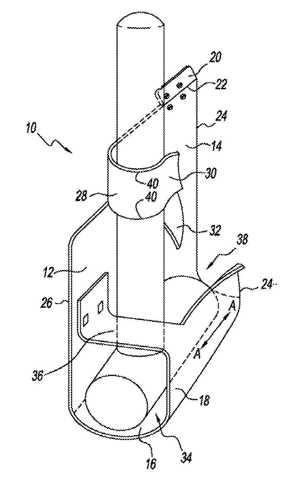
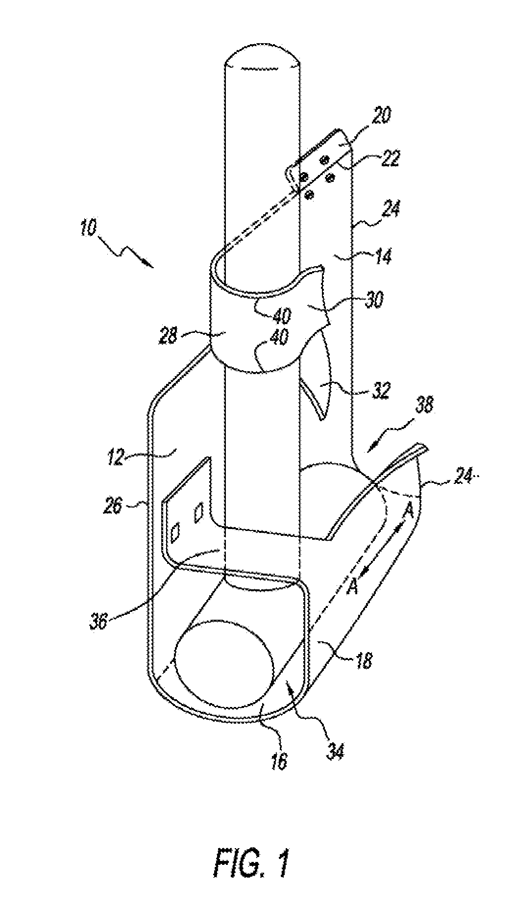
[0029]Referring to FIG. 1, there is shown a perspective view of a claw hammer locked in place in an upright position in a tool holder 10 in accordance with the principles of the invention. The hammer holder 10 can be made from a single piece of material 12 such as leather, heavy canvas, plastic, etc., where the preferred material is a plastic of resinous material.

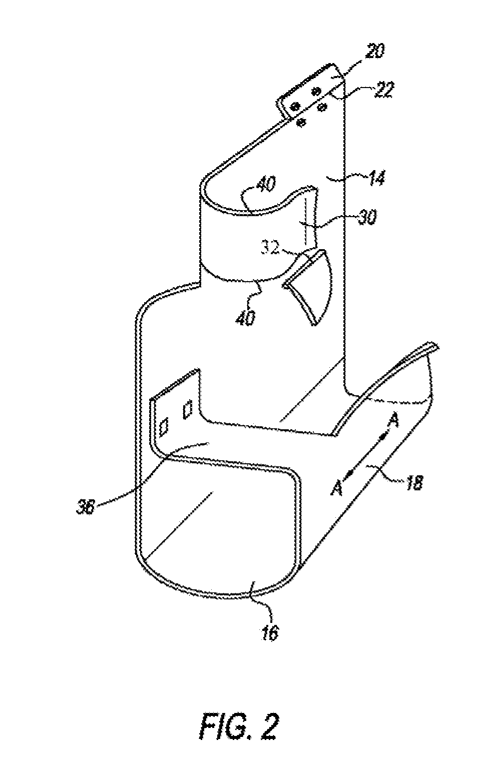
[0030]The holder has a support member or rear section 14, a bottom section 16, and a front section 18. The rear section includes at its top a fold over tab 20 that can bend about a scored fold line 22 and includes two openings which, when the tab is folded backward and rests against the back of the rear section, are aligned with two openings in the rear section. The openings are provided for receiving rivets or screws for attaching the holder to a utility belt, a worker's garment, a side of a tool bag, a nail pouch, etc.

[0031]The bottom section 16, which is a continuation of the rear section 14, is bent outward along a fold...


PUM


Abstract

A hammer holder having a support member for attachment to a belt, garment, tool bag or nail pouch of a hammer user. The hammer holder includes a U shaped chamber integrated with the support member and provides support for the hammer head and for the hammer handle in an upright vertical position when the support member is connected to a belt or a user. The chamber is large enough to contain the head of the hammer and includes stop means which prevents the head of the hammer from passing through the chamber or out the top of the chamber. A clip is attached to the support member for receiving the vertically oriented handle of the hammer and a movable gate member pivotally attached to the support member permits the hammer handle to move into the clip and spring back to prevent the handle from moving out of the clip.

Description

BACKGROUND OF THE INVENTION[0001]1. Field of the Invention[0002]The present invention relates generally to a tool holder and more specifically to a holder for a hammer that is adapted to be attached to a worker's belt, garment, tool bag or nail pouch, a holder which, when located on a worker's utility belt, can hold a hammer captive whether the worker is jumping, knelling or bending or even when the holder is upside down or subjected to heavy motion, a holder into which a hammer can be inserted into and removed from with one hand and, because the hammer is in its upright position, it is ready for use by the worker immediately upon removal.[0003]2. Description of Related Art[0004]Carpenters and tradesmen often use a utility belt to hold their various tools, one of which is usually a claw hammer which is located in a metal loop attached to the worker's belt. In use, when a worker requires the use of another tool, he / she will place the hammer in the loop on his / her utility belt. To do ...

Claims


Application Information

Patent Timeline
Patent Type & Authority Applications(United States)
IPC IPC(8): A45F3/00
CPCA45F5/02A45F2200/0575A45F2200/0566A45F5/021
Inventor KREITZER, DANIEL WADE
Owner KREITZER DANIEL WADE
Why Eureka
Try Eureka