Positioning rack module and an electronic device assembly incorporatiing the same

Inactive Publication Date: 2011-12-01
AOPEN
View PDF2 Cites 14 Cited by
  • Summary
  • Abstract
  • Description
  • Claims
  • Application Information

AI Technical Summary

Benefits of technology

[0006]Therefore, the object of the present invention is to provide a positioning rack module for support

Problems solved by technology

However, the problem with this kind of arrangement is that since the space between the display device and the wall is too narrow for performing maintenance on

Method used


Image

  • Positioning rack module and an electronic device assembly incorporatiing the same
  • Positioning rack module and an electronic device assembly incorporatiing the same
  • Positioning rack module and an electronic device assembly incorporatiing the same

Examples


Embodiment Construction

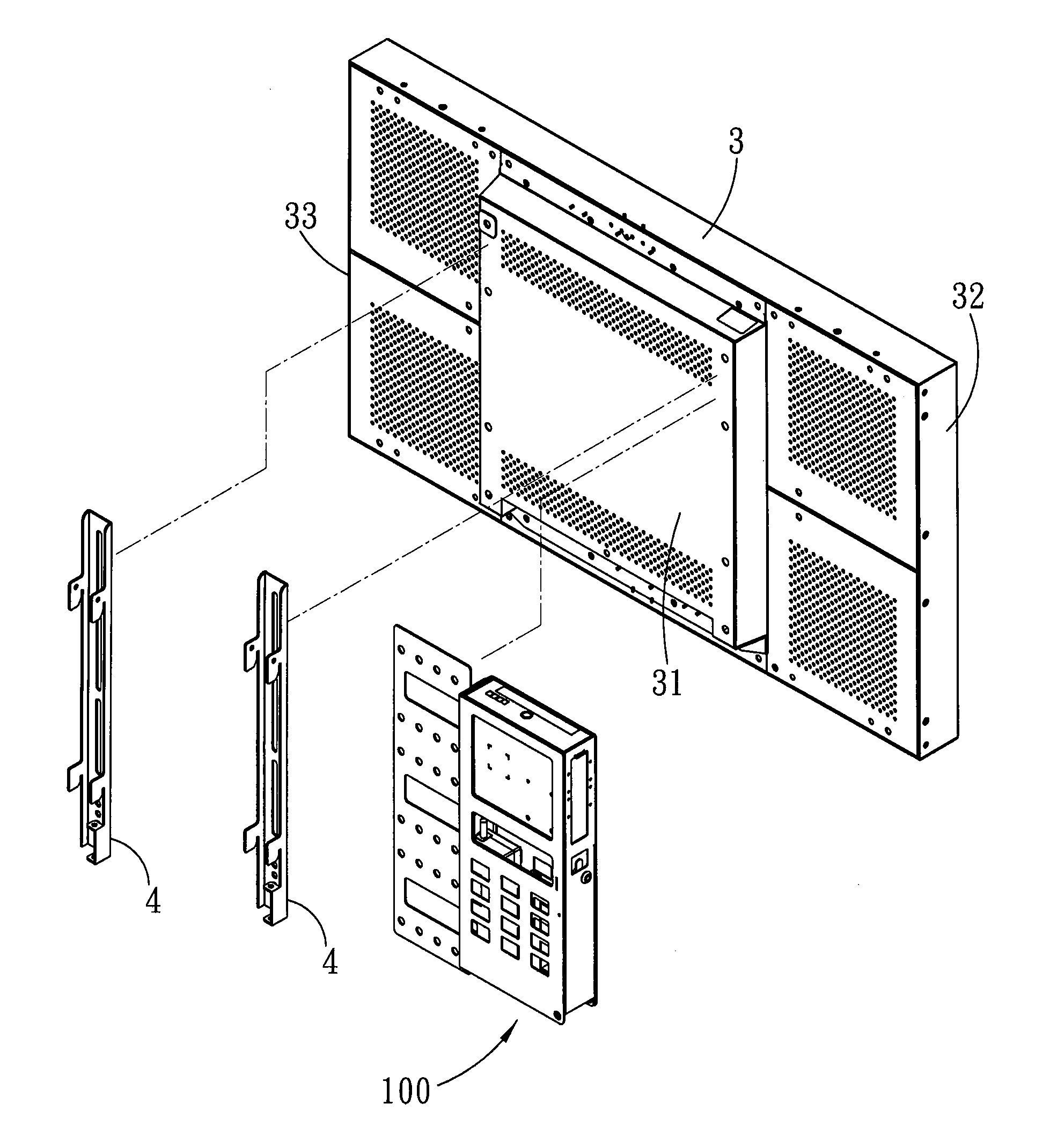
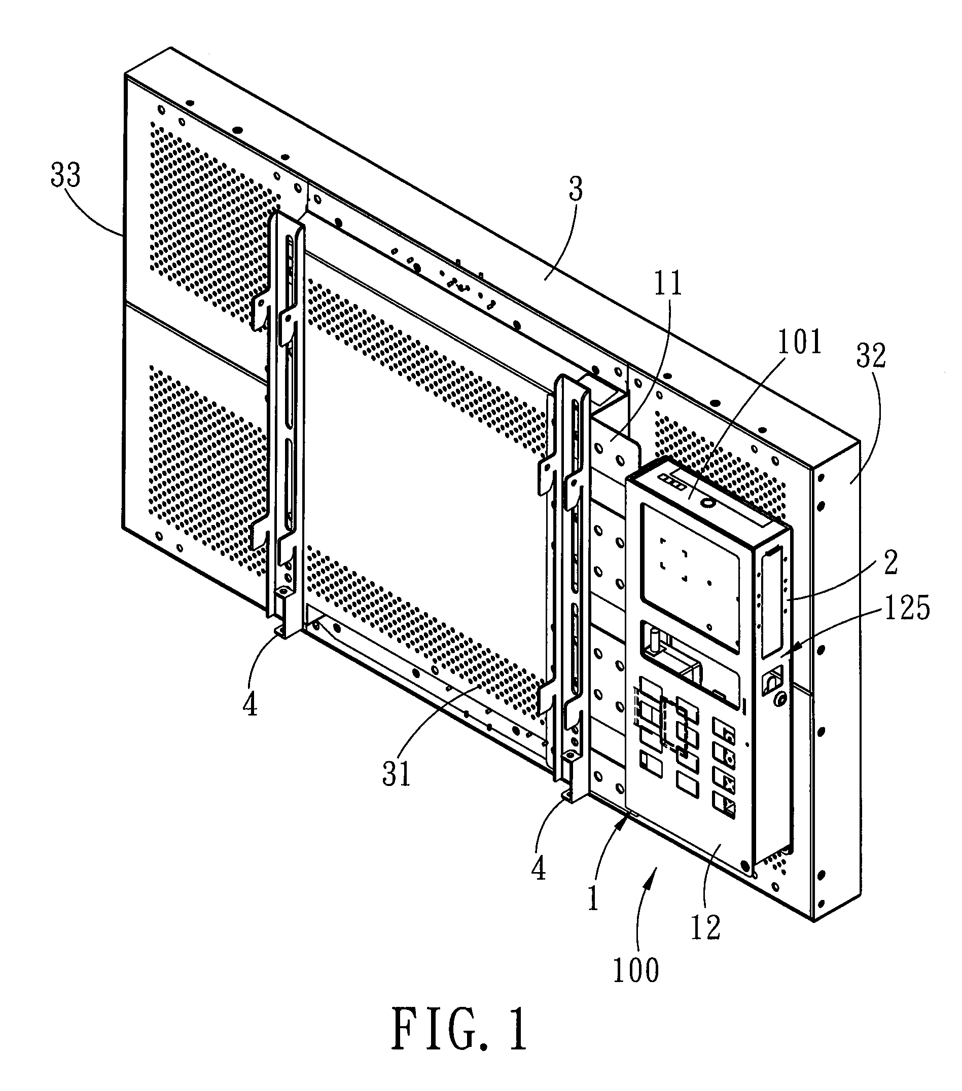
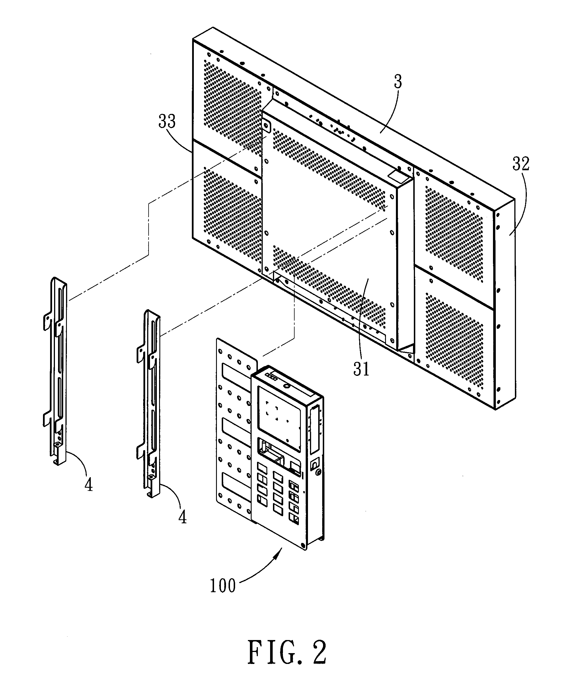
[0031]With reference to FIG. 1 and FIG. 2, the preferred embodiment of a positioning rack module 100 according to the present invention is for supporting a computer 101 at a backside 31 of a display device 3, such that while the display device 3 is mounted to a wall through a wall mounting rack 4 thereof, the positioning rack module 100 can be secured between the backside 31 and the wall mounting rack 4 of the display device 3, and can thereby support the computer 101 (which is a barebone in this embodiment) on the wall as well.

[0032]With reference to FIG. 1 and FIG. 3, the positioning rack module 100 includes a movable frame 2. The movable frame 2 includes a movable frame body 21 to be disposed at the backside 31 of the display device 3, and a first receiving portion 22 formed in the movable frame body 21 for receiving the computer 101. The movable frame body 21 is operable to move relative to the display device 3 between a hidden position (as shown in FIG. 7) and an exposed positi...


PUM


Abstract

A positioning rack module for supporting a computer at a backside of a display device includes a movable frame. The movable frame includes a movable frame body to be disposed at the backside of the display device, and a first receiving portion formed in the movable frame body for receiving the computer. The movable frame body is operable to move relative to the display device between a hidden position and an exposed position. The movable frame body is hidden behind the backside of the display device when disposed at the hidden position. The movable frame body extends beyond a lateral side of the display device when disposed at the exposed position.

Description

CROSS-REFERENCE TO RELATED APPLICATION[0001]This application claims priority of Taiwanese Application No. 099210276, filed on May 31, 2010.BACKGROUND OF THE INVENTION[0002]1. Field of the Invention[0003]The invention relates to a positioning rack module and an electronic device assembly, more particularly to a positioning rack module for supporting a computer at a backside of a display device and to an electronic device assembly including a display device and the positioning rack module.[0004]2. Description of the Related Art[0005]Currently, a flat panel monitor is generally constituted by a wall-mounted display device that is equipped with a host computer (e.g., a barebone) for hanging on the wall. For aesthetic reasons, the computer is normally mounted at the backside of the display device such that when the display device is hung, the computer is disposed between the backside of the display device and the wall. However, the problem with this kind of arrangement is that since the ...

Claims


Application Information

Patent Timeline
IPC IPC(8): H05K7/18F16M13/02F16L3/08H05K7/14
CPCH05K5/0204G06F1/16F16M13/00F16M13/02G06F1/1607G06F2200/1631
Inventor LIN, TE-ANCHEN, CHIH-HSIUNG
Owner AOPEN
Why Eureka
Try Eureka