Device And Method For Explosive Forming

a technology of explosive forming and tubular work, applied in the field of metal forming, can solve the problems of affecting the overall machining time of the work piece, and requiring individual working steps, so as to reduce the final machining time and therefore the overall machining time of the work piece, and simplify the effect of accelerating the change of the work pi

Active Publication Date: 2012-02-02
COSMA ENG EURO AG
View PDF1 Cites 0 Cited by
  • Summary
  • Abstract
  • Description
  • Claims
  • Application Information

AI Technical Summary

Benefits of technology

[0047]The work piece can be provided with at least one hole during explosive forming. Integration of an additional work step, namely, perforation, in the actual forming process reduces the final machining time and therefore the overall machining time of the work piece. The separated hole material can be discarded. This simplifies and accelerates work piece change.

Problems solved by technology

This method, although it gets by without any liquid, is relatively complicated and time-consuming to handle.
All these are time-intensive individual working steps.
However, the latter is a part subject to wear, which causes additional costs.
This complicated handling results in high time expenditure and therefore costs.
This method, consequently, has not gained acceptance industrially.

Method used


Image

  • Device And Method For Explosive Forming
  • Device And Method For Explosive Forming
  • Device And Method For Explosive Forming

Examples


Embodiment Construction

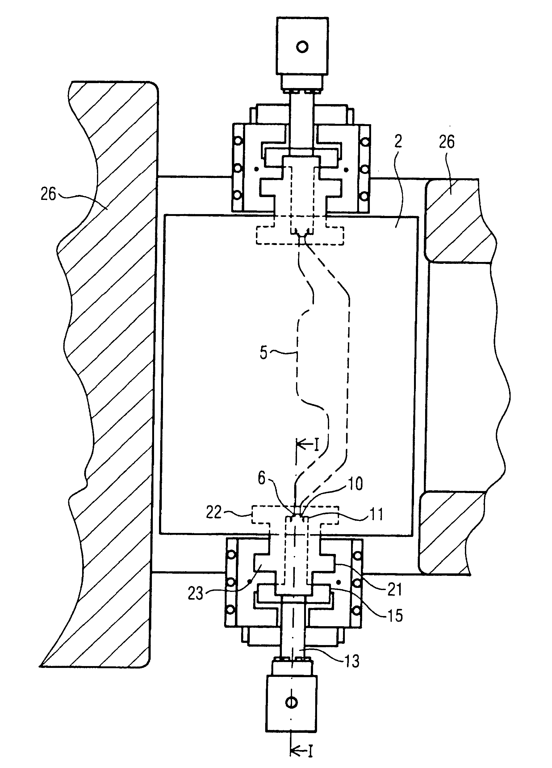
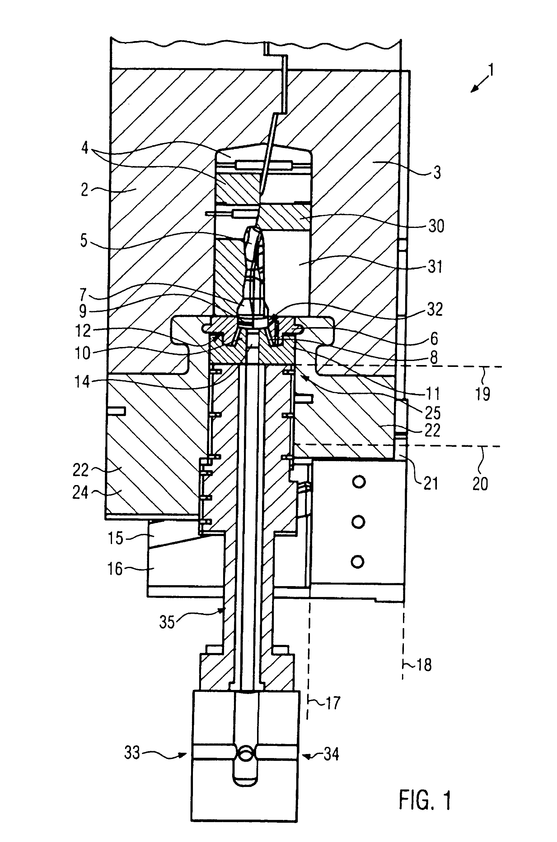
[0054]FIG. 1 shows a vertical section through the device. The multipart forming die 1 here is shown in the closed state and consists in this practical example of an upper 2 and lower 3 forming die half. The actual die mold or contour is produced by the die inserts 4, which are inserted in the upper 2 and lower 3 forming die halves and mechanically connected to them. The die contour, however, can also be introduced directly into the upper 2 and lower 3 forming die halves. In the closed state, the mold halves form a die cavity 5 in their interior that corresponds to the final shape of the work piece after the forming process.

[0055]In order for the work piece to come in contact with die cavity 5 during the forming process, the forming die 1 is provided with venting openings (not shown). These are preferably arranged gap-like along the die contour. The air contained in the die cavity 5 can thus escape and not hamper the work piece in its expansion. In addition, a more uniform temperatur...


PUM

PropertyMeasurementUnit
areaaaaaaaaaaa
thicknessaaaaaaaaaa
shapeaaaaaaaaaa

Abstract

A device for explosive forming of a tubular work piece includes a multipart explosive forming die, which defines a forming area having an inner surface corresponding to a final shape of the tubular work piece and a nozzle arrangement disposed adjacent to the forming area. The device also includes a plug for forming a seal by simultaneously deforming an end of the work piece and clamping the deformed end between the plug and a facing surface of the nozzle arrangement. In this way, the work piece itself contributes to the sealing of an internal explosion space. With insertion of new work piece blanks, and introduction of the plug during each individual forming process, new seals are produced in a convenient manner during subsequent forming processes. The device supports a simplified handling approach and integrates several functions into one working step, resulting in a shorter cycle times and cost-effective industrial production.

Description

CROSS-REFERENCE TO RELATED APPLICATIONS[0001]This is a Continuation Patent Application which claims the benefit of U.S. patent application Ser. No. 11 / 916,056 filed Dec. 20, 2007 entitled “Device And Method For Explosion Forming” which claims the benefit as a 371 U.S. National Stage Application from International Application No. PCT / EP2006 / 003435 filed Apr. 13, 2006 which claims the benefit of DE 10 2005 025 660.0 filed Jun. 3, 2005, the entire disclosures of the applications being considered part of the disclosure of this application, and hereby incorporated by reference.FIELD OF THE INVENTION[0002]The invention relates generally to metal forming and more particularly to a device and method for explosive forming of tubular work pieces.BACKGROUND OF THE INVENTION[0003]Different devices and methods exist for forming of a work piece. During hydro-forming, for example, a tubular work piece is filled with a liquid, generally water, and sealed. By increasing the liquid pressure, the work...

Claims


Application Information

Patent Timeline
Patent Type & Authority Applications(United States)
IPC IPC(8): B21D26/08B21J5/04
CPCY10S72/706B21D26/08
Inventor TRUBERT, FRANZZAK, ALEXANDERSTRANZ, ANDREAS
Owner COSMA ENG EURO AG
Why Eureka
Try Eureka