
Centrifugal clutch apparatus

a centrifugal clutch and clutch body technology, applied in mechanical devices, couplings, clutches, etc., can solve the problems of increasing manufacturing costs, vibration isolating rings mounted on the outer circumferential surface of the driving plate slipping off from the driving plate, etc., to reduce manufacturing costs, reduce manufacturing costs, and reduce the generation of “clutch squeal

Active Publication Date: 2013-01-24
FCC KK
View PDF9 Cites 1 Cited by
  • Summary
  • Abstract
  • Description
  • Claims
  • Application Information

AI Technical Summary

Benefits of technology

The invention provides a centrifugal clutch apparatus that is simpler and less expensive than previous versions, while also reducing the risk of slippage and suppressing the generation of "clutch squeal." This is achieved by using a vibration reducing member in contact with an inner surface of a portion of the centrifugal clutch and a tension member that can be snap-fitted into a groove and held in a radially-outward-biased condition. The tension member can be formed as an annular member with a cut-off portion or bent portions that hold the member in the groove. The technical effects include reducing manufacturing costs, simplifying the construction of the clutch apparatus, and suppressing the generation of "clutch squeal."

Problems solved by technology

Because the centrifugal clutch apparatus of the prior art noted above requires a press-formed vibration isolating ring having a complicated configuration, the manufacturing cost can be very high.
In addition, there is the risk that a vibration isolating ring mounted on the outer circumferential surface of the driving plate would slip off from the driving plate due to the centrifugal force on the isolating ring.
This method of crimping can also increase the manufacturing cost.

Method used


Image

  • Centrifugal clutch apparatus
  • Centrifugal clutch apparatus
  • Centrifugal clutch apparatus

Examples


Embodiment Construction

[0041]Several embodiments of the present disclosure are described below with reference to accompanied figures.

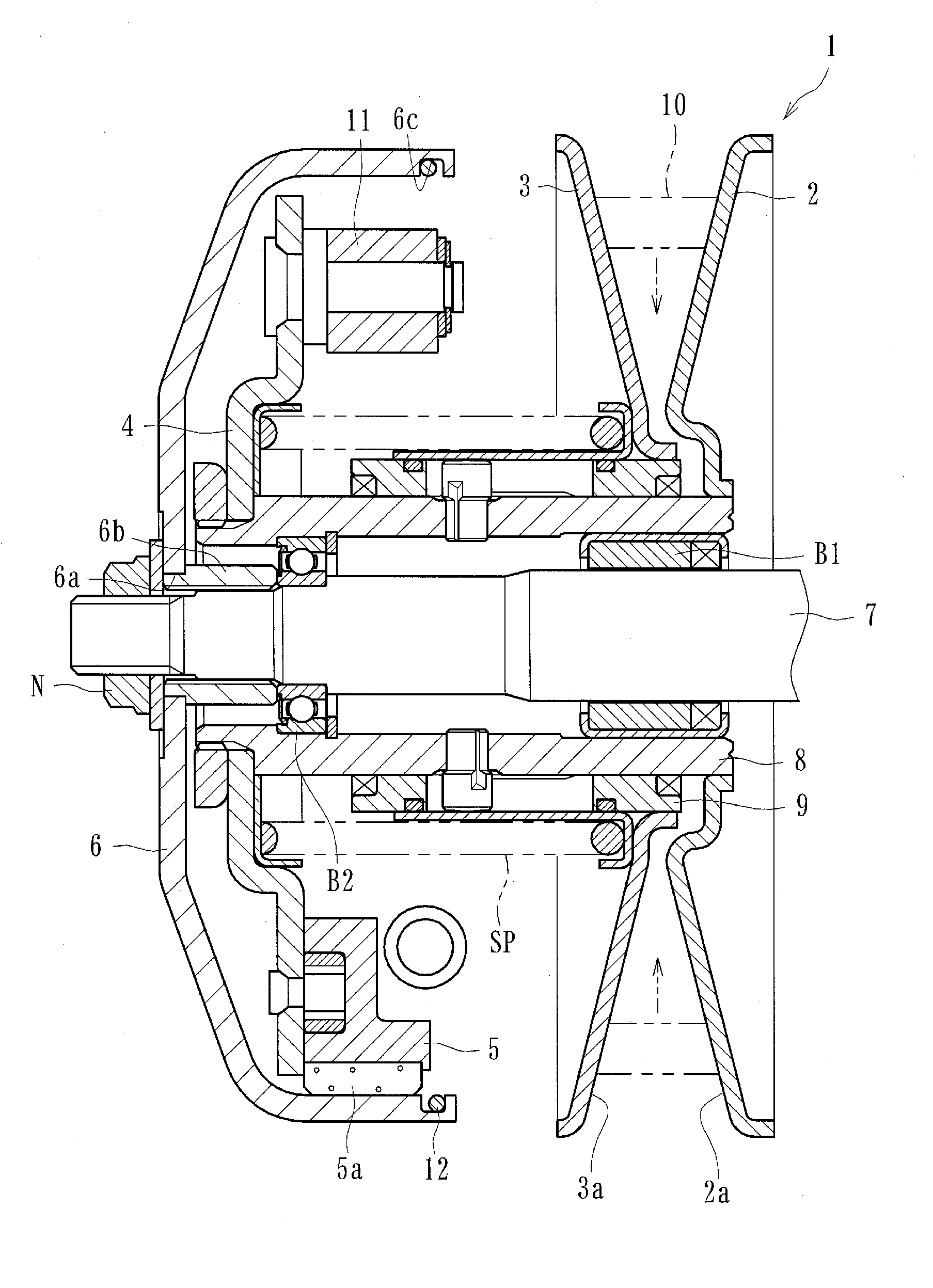
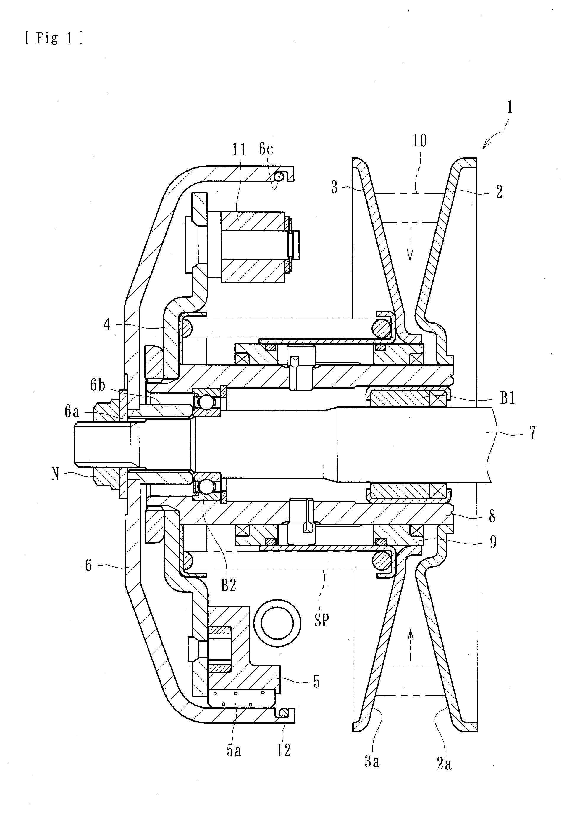
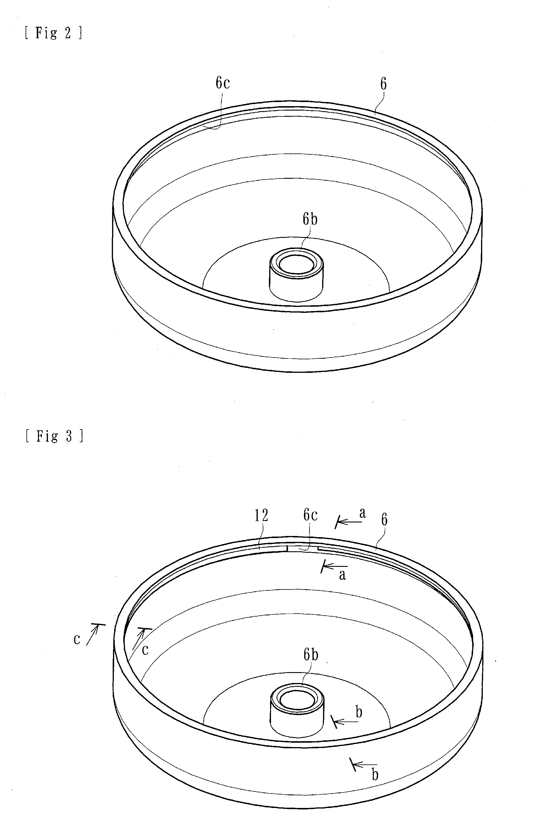
[0042]At least one of the embodiments of centrifugal clutch apparatuses disclosed herein can be applied to a centrifugal clutch apparatus of a motorcycle (e.g., a scooter) for transmitting and cutting off the driving power of the engine of the motorcycle to the wheels or other portions of the motorcycle. The centrifugal clutch can comprise, as shown in FIG. 1, a driven pulley 1, a driving plate (driving-side rotational member) 4, clutch devices 5, an output housing (driven-side rotational member) 6, friction members 5a, and a tension member 12.

[0043]The driven pulley 1 can be driven by a V belt 10 (endless belt) which can be made of plastic resin or other materials. The V belt 10 can be driven by a driving pulley (not shown) rotated by an engine (driving device) of a motorcycle. The driven pulley 1 can comprise an axially immovable sheave 2 and an axially movable sheave 3 fo...


PUM


Abstract

A centrifugal clutch apparatus can include a driving-side rotational member rotatable around a shaft member connected to a driving device; clutch devices mounted on the driving-side rotational member and movable radially-outward of the driving-side rotational member. A driven-side rotational member rotatable independent from the driving-side rotational member can be arranged for covering the driving-side rotational member and can have an inner circumferential surface to engage with the clutch devices. Friction members can be adapted to be abutted against the inner circumferential surface so as to transmit the driving power of the driving device to the driven-side rotational member. The inner circumferential surface of the driven-side rotational member can be formed with a groove and a tension member formed as a ring-shaped member can be snap-fitted into the groove and held therein under a radially-outward biasing force.

Description

CROSS-REFERENCE TO RELATED APPLICATIONS[0001]This is a continuation of PCT Application No. PCT / JP2011 / 051599, filed on Jan. 27, 2011, which claims priority to Japanese Patent Application No. 2010-015839, filed on Jan. 27, 2010. The foregoing applications are hereby incorporated by reference herein in their entirety.BACKGROUND OF THE DISCLOSURE[0002]1. Field of the Disclosure[0003]The present inventions relates to centrifugal clutch apparatuses for transmitting and cutting off the driving power of a driving device (e.g., engine of a motorcycle) to a driven device (e.g., a transmission of a motorcycle). Some of the embodiments disclosed herein are configured to connect and / or disconnect a driving-side rotational member to an inner circumferential surface of a driven-side rotational member via friction members.[0004]2. Description of the Related Art[0005]Clutch apparatuses are usually arranged in a power transmission train for transmitting the driving power of an engine of vehicle (e.g...

Claims


Application Information

Patent Timeline
Patent Type & Authority Applications(United States)
IPC IPC(8): F16D43/18
CPCF16D43/18F16D2043/145F16D2300/22
Inventor KATAOKA, MAKOTOYAMAGISHI, MASAHIROMIWA, NAOYUKIMURAI, MASATAKAAONO, KAORU
Owner FCC KK
Learn More