

Mmw low sidelobe constant beamwidth scanning antenna system
a scanning antenna and low sidelobe technology, applied in the field of reflector antennae, can solve the problems of aircraft and persons within the aircraft being damaged, crashed, etc., and achieve the effect of increasing the frequency of operation of the reflector antenna
- Summary
- Abstract
- Description
- Claims
- Application Information
AI Technical Summary
Benefits of technology
Problems solved by technology
Method used
Image

Examples
Embodiment Construction
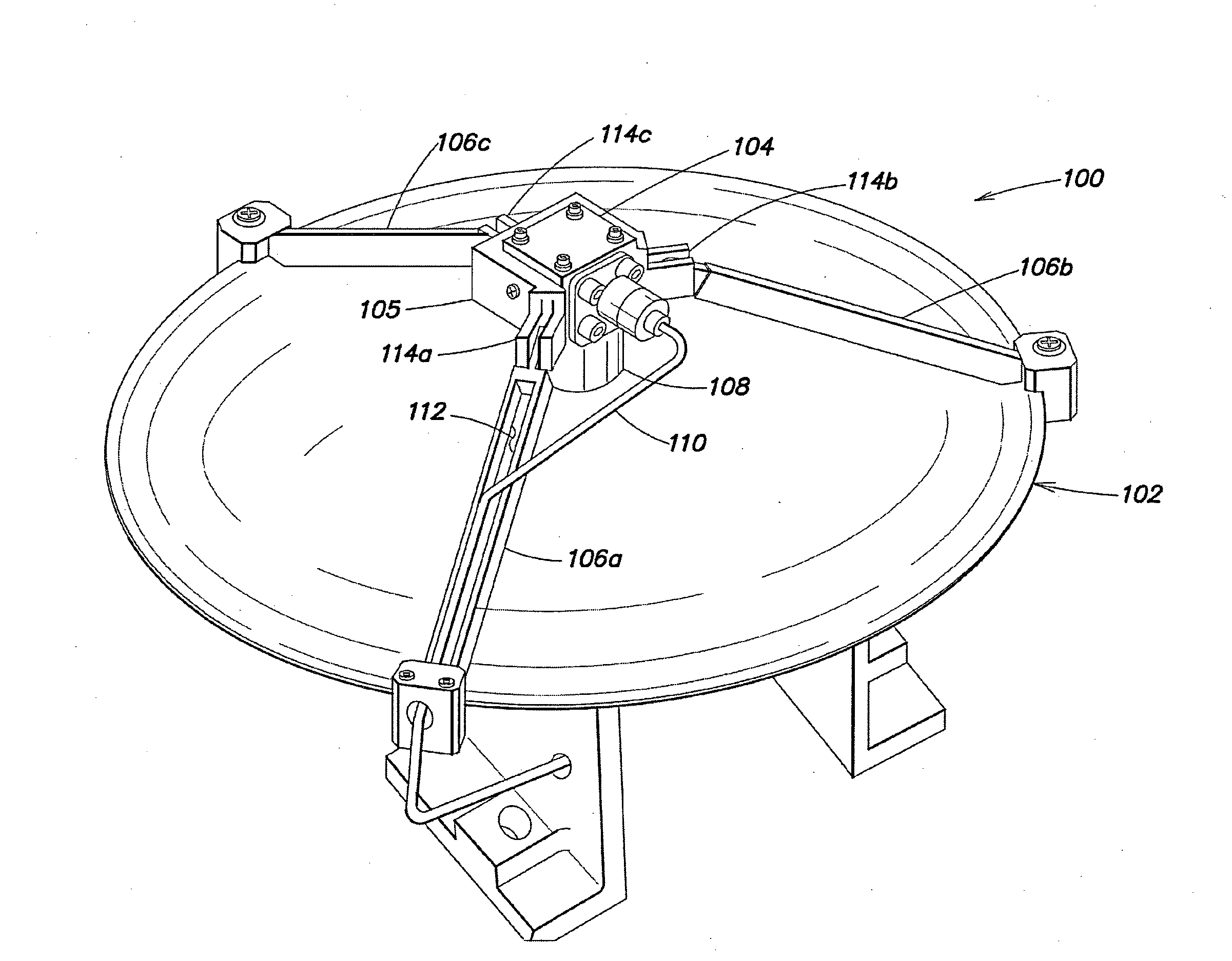
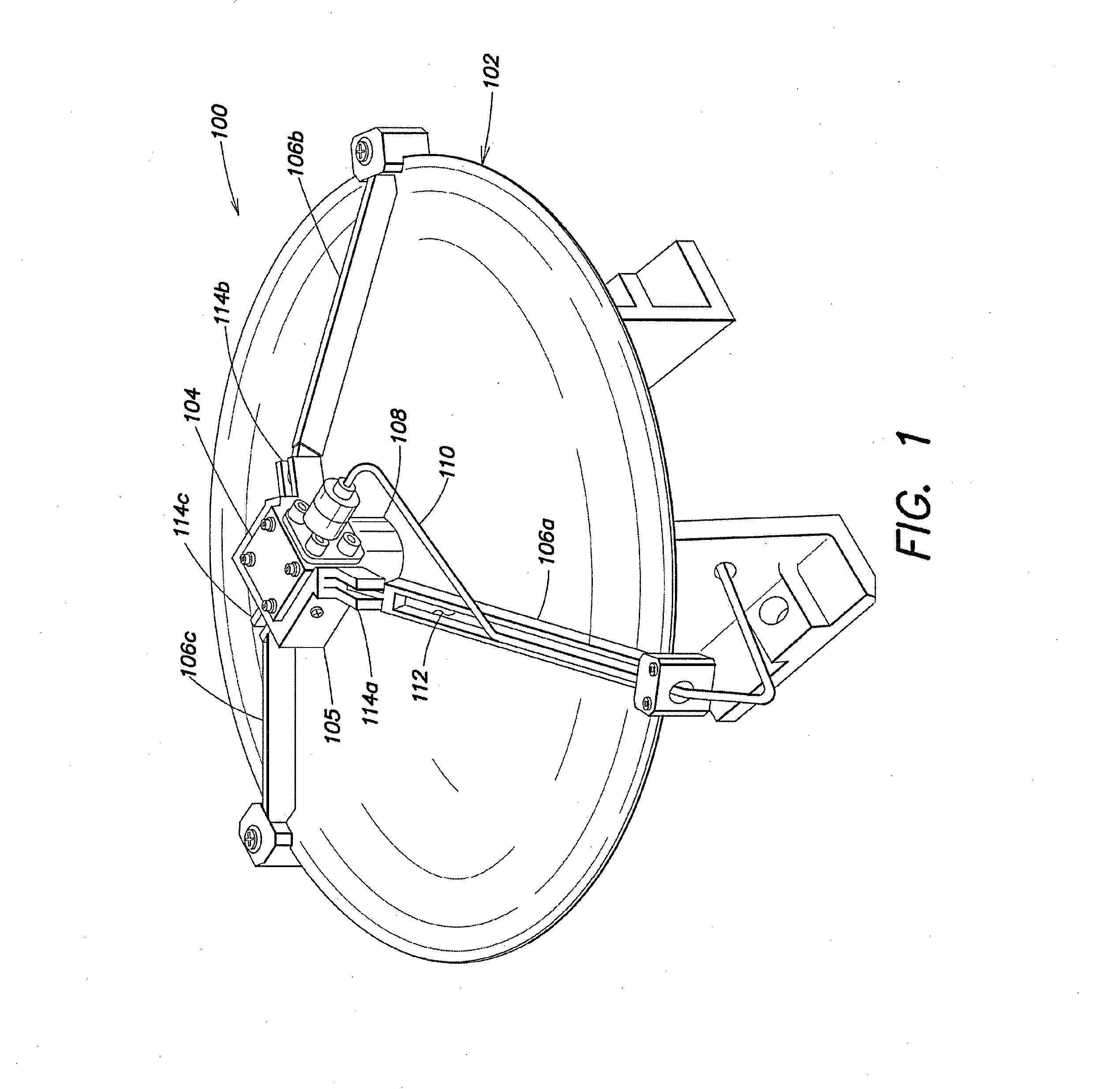
[0019]Applicants have appreciated that it may be desirable to provide antennae suitable for being mounted on aircraft and suitable for detecting small objects, such as cables. Thus, according to one aspect of the present application, a reflector antenna suitable for detecting objects as small as ⅜ of an inch, or smaller, is provided, that is also sufficiently small to be suitable for mounting on aircraft. According to a non-limiting embodiment, the antenna may be configured to operate at the millimeter wavelength (mmW) range, such as, for example, between approximately 30 GHz and approximately 38 GHz. According to a non-limiting embodiment, the antenna may include an offset corrugated feed horn and a reflector dish, coupled together by one or more feed arms.
[0020]Applicants have appreciated that detection of certain objects with an antenna may be facilitated by operation of the antenna at mmW frequencies. Cables, as a non-limiting example, may be relatively small, ranging in diamete...
PUM
 Abstract
Description
Claims
Application Information