Switch-equipped coaxial connector

a coaxial connector, switch-equipped technology, applied in the direction of two-part coupling devices, coupling device connections, testing/measuring connectors, etc., can solve the problems of reduced height, increased size of the whole connector, and poor durability of the coaxial connector, so as to ensure the flexibility improve the performance of the contact between the opposing connector and the contact, and increase the span length of the elastic beam-like member

a coaxial connector, switch-equipped technology, applied in the direction of two-part coupling devices, coupling device connections, testing/measuring connectors, etc., can solve the problems of reduced height, increased size of the whole connector, and poor durability of the coaxial connector, so as to ensure the flexibility improve the performance of the contact between the opposing connector and the contact, and increase the span length of the elastic beam-like member

US20130102173A1Inactive Publication Date: 2013-04-25DAIICHI SEIKO CO LTD

Image

  • Switch-equipped coaxial connector
  • Switch-equipped coaxial connector
  • Switch-equipped coaxial connector

Examples


Embodiment Construction

[0039]Hereinafter, an embodiment in which a switch-equipped coaxial connector according to the present invention is employed as a circuit test switch will be explained in detail based on drawings.

[About Overall Structure of Circuit Test Switch]

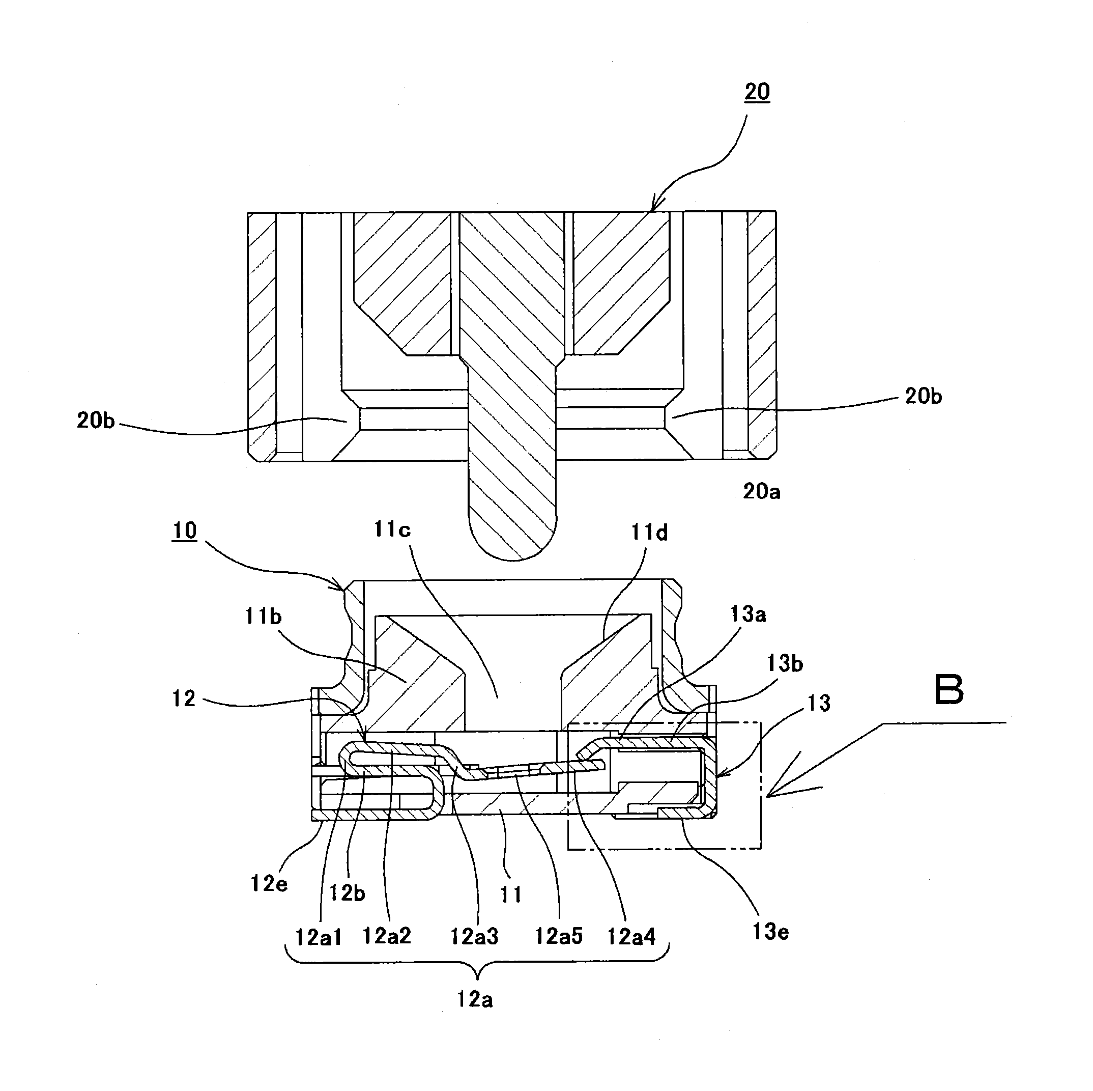
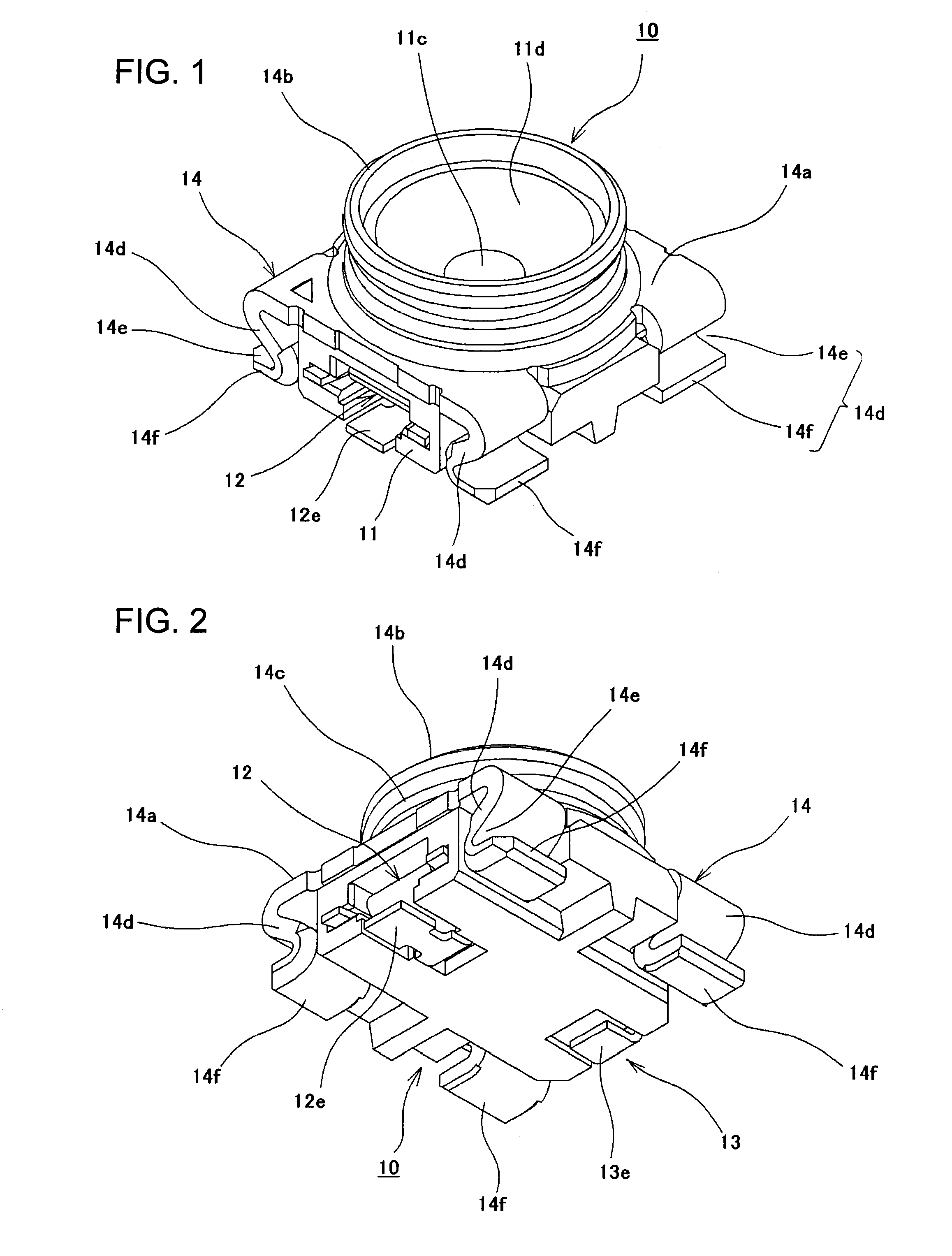
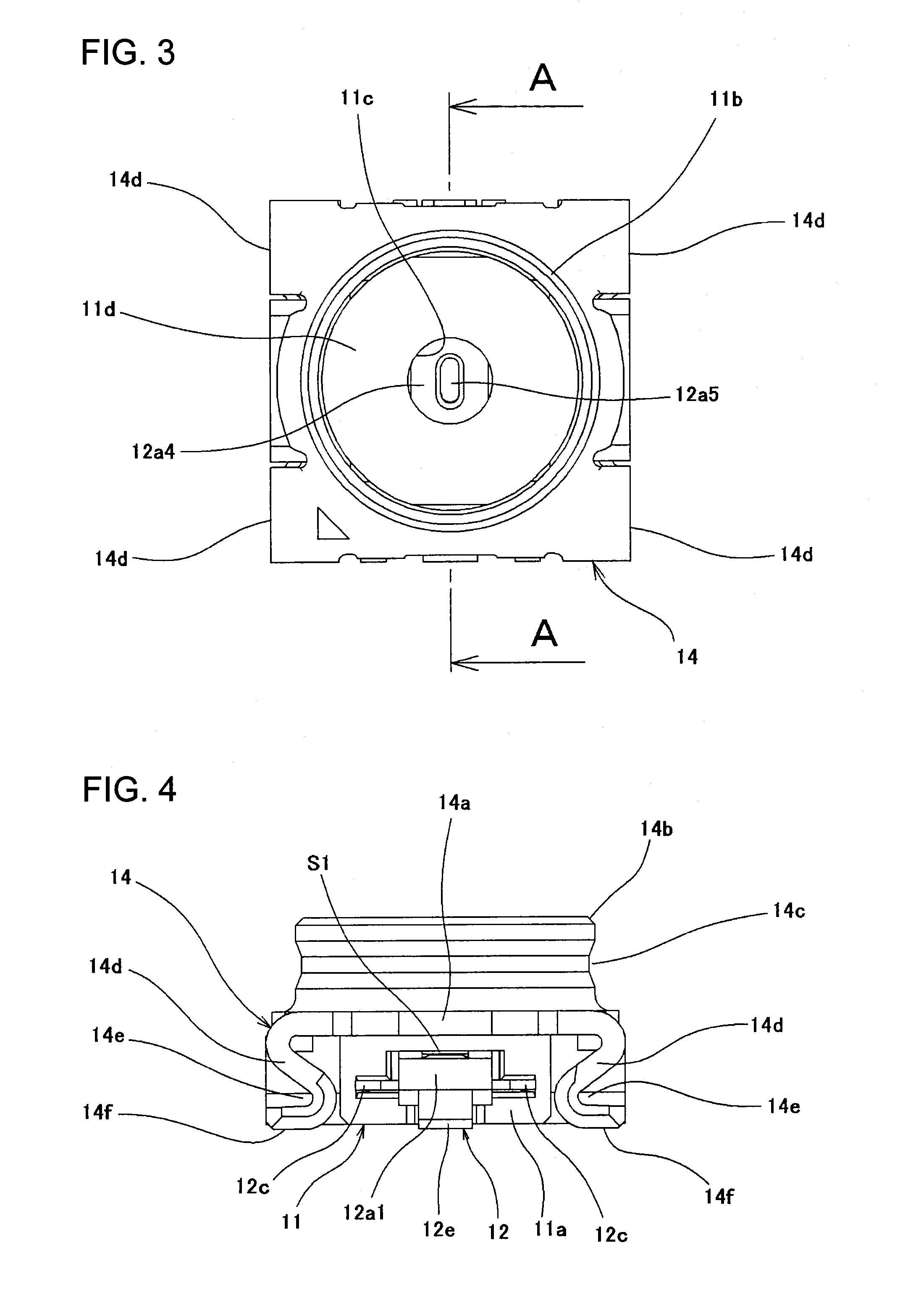
[0040]The switch-equipped coaxial connector 10 according to a first embodiment of the present invention shown in FIG. 1 to FIG. 6 and FIG. 10 to FIG. 12 is mounted on a wiring board, of which illustration is omitted, and a test plug connector 20 (see FIG. 11 and FIG. 12) serving as an opposing connector is configured to be mated with the switch-equipped coaxial connector 10 from the upper side or removed therefrom toward the upper side. More specifically, the test plug connector 20 disposed in the upper side of the switch-equipped coaxial connector 10 is thrust into the switch-equipped coaxial connector 10 in the lower side with appropriate force while being held by hands of an operator, and an attached state that both of the connectors are ma...


PUM


Abstract

With a simple configuration, increase in size can be avoided, usage durability is improved, and occurrence of insufficient electrical connection caused by dust can be prevented well. A crank part is provided in at least one of both contacts including elastic beam-like members. Both of the contacts are provided with cut-away parts, which substantially increase the span lengths of the elastic beam-like members, and gaps between the contacts and an insulating housing which ensure flexibility of the elastic beam-like members to ensure flexibility and prevent permanent deformation of the contacts while enhancing elasticity of the contacts. Dust which has entered the interior thereof is moved along the crank part to ensure electrical conductivity well, which is an employed configuration.

Description

BACKGROUND OF THE INVENTION[0001]1. Field of the Invention[0002]The present invention relates to a switch-equipped coaxial connector provided with a pair of contacts caused to be in a mutually-separated state when an opposing connector is mated.[0003]2. Description of Related Art[0004]Generally, a switch-equipped coaxial connector is used in an electronic device or an electric device such as a mobile phone. Such a switch-equipped coaxial connector is used as, for example, a small circuit test switch for testing the state or performance of various electronic circuits such as high-frequency circuits provided in the device. Each of circuit test switches disclosed in below-described Japanese Patent Application Laid-Open No. H09-245907, Japanese Patent Application Laid-Open No. 2002-359039, etc. is composed of a switch-equipped coaxial connector mounted on a circuit board so as to disconnect an electronic circuit of a main body of the device and is configured so that a probe (test needle...

Claims


Application Information

Patent Timeline
25 Apr 2013
Publication
US20130102173A1
IPC
H01R29/00
CPC
H01R13/7033; H01R24/46; H01R13/70; H01R2201/20; H01R24/50; H01R24/20
Inventors
HASHIMOTO, YOICHI; YAMAUCHI, TAKAO