Electromechanical billboard

a technology of electromechanical and billboard, applied in the field of optical systems and elements, can solve the problems of loss of display elements, wear on the display apparatus, difficult manufacture, assembly and maintenance, etc., and achieve the effects of improving viewability, improving contrast, and simplifying the apparatus

Inactive Publication Date: 2013-07-11
BROWN KEDRICK F
View PDF1 Cites 0 Cited by
  • Summary
  • Abstract
  • Description
  • Claims
  • Application Information

AI Technical Summary

Benefits of technology

[0024]The present invention uses neither transparent display element casings, nor fluid. Rather to simplify the apparatus, gravity and friction are used to keep display elements from drifting from their angular orientations with respect to a viewer in a vertically oriented display when the driving electric fields are off. Other optional means may be used to inhibit stray motion of display elements on their axles (e.g. axles with frictional surfaces) if axles are horizontal.
[0025]To improve viewability, the present invention preferably employs one or two eared brackets to hold the display elements in an elevated position above the plane of the tray partition walls. In this way, the leading edge of a display element is extended above the surface of the display, which improves the contrast and alters the degree of electrical shielding of the display elements by the partition walls.
[0026]The present invention uses a single axle for an entire column of display elements, which fixes each display element's axis of rotation and retains it in place when the display is oriented vertically and even upside down. This structural feature also eliminates color blurring when the display element's electret poles are aligned with its driving electric field. An axle is not present in any prior art with microscopic display elements.
[0027]The present invention uses a parallelepiped display element that shows two faces to the user over a very broad range of viewing angles.
[0028]With the present invention, each bicolor display element is unique in that it may be colored both white and an ink color that enables it to display a portion of a separated single-color / white image associated with an established ink printing process requiring multiple inks.
[0029]A primary advantage of the present invention is that it provides a novel technology for a large-scale, color electronic-paper display that exhibits high contrast under ambient light, and is able to display a very wide variety of images without replacing any elements of the display.

Problems solved by technology

In such existing art, microcapsules may collide with each other within the display or collide with the internal surface of the cells housing them, causing wear on the display apparatus.
The L-shaped brackets in this type of display can lead to the loss of display elements should the display be tilted to its side or turned face down.
This type of display has numerous components, such as a separately operable axle on each display element, and is difficult to manufacture, assemble and maintain.
Materials capable of producing a magnetic shielding effect by redirecting magnetic field lines can also be saturated, and may be relatively expensive as in the case of mu-metal.

Method used


Image

  • Electromechanical billboard
  • Electromechanical billboard
  • Electromechanical billboard

Examples


Embodiment Construction

[0049]In the following description, reference is made to the accompanying drawings, which form a part hereof and which illustrate several embodiments of the present invention. The drawings and the preferred embodiments of the invention are presented with the understanding that the present invention is susceptible of embodiments in many different forms and, therefore, other embodiments may be utilized and structural, and operational changes may be made, without departing from the scope of the present invention.

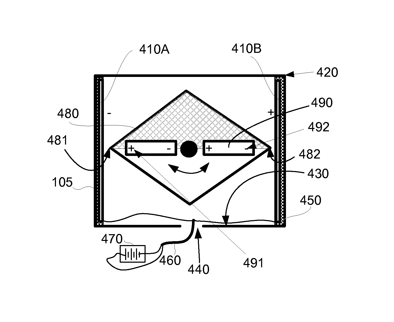
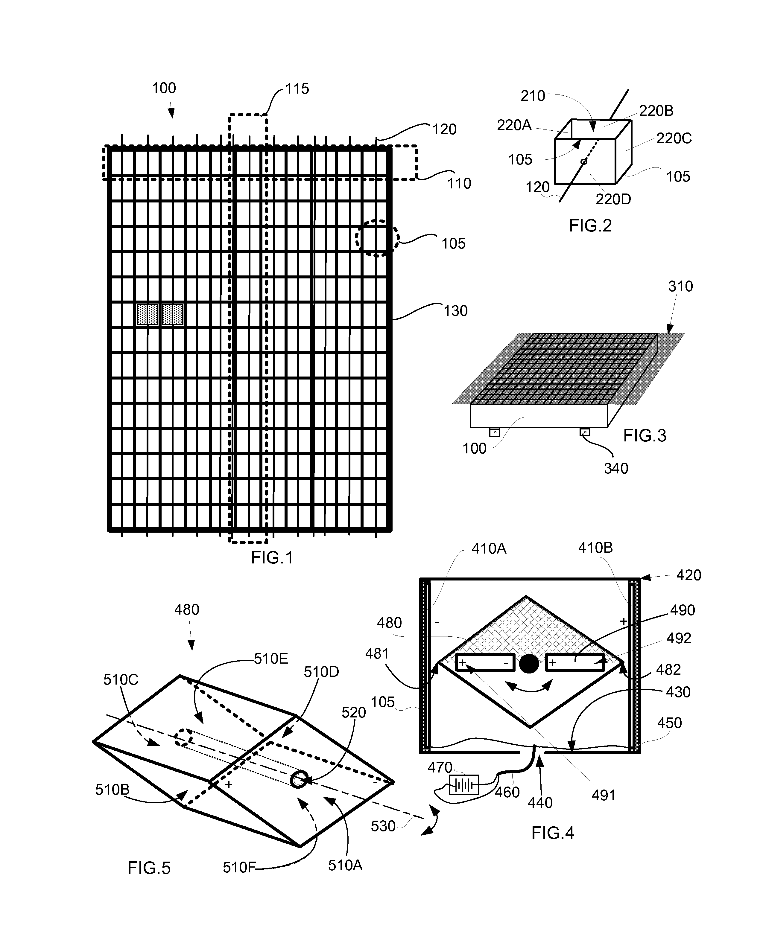
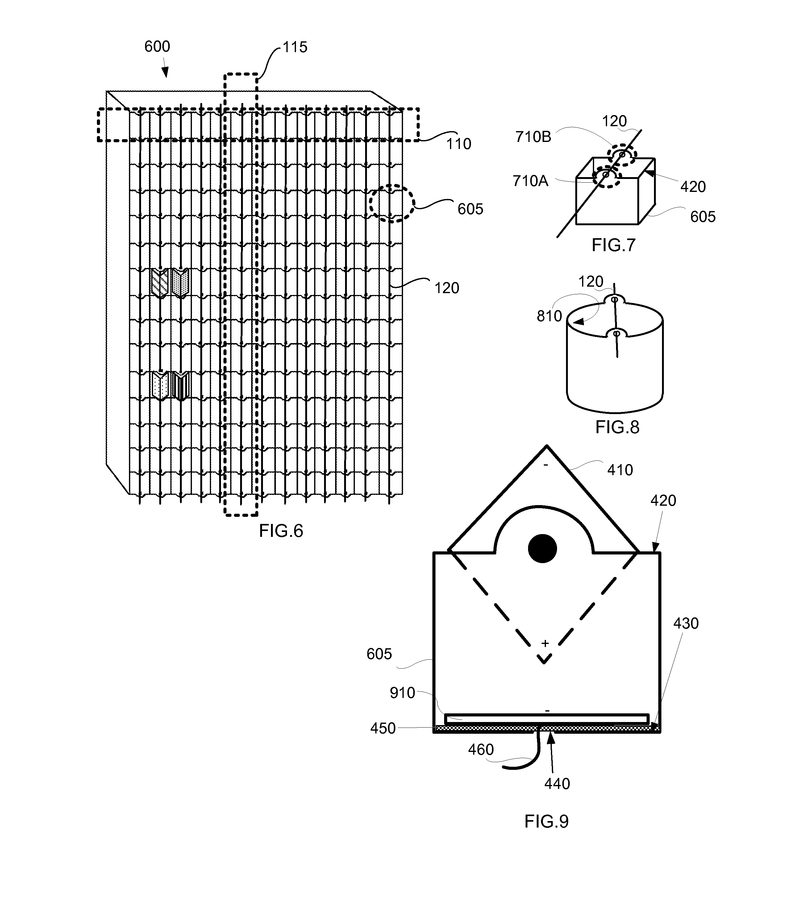
[0050]In short, the claimed apparatus is an electromechanical image display that includes a box-structure (100); an axle (120); a cup (105) replicated in a row and column matrix; an axle (120) for each column of cups; one or more electric-field-generating conducting plates, such as a first electric-field-generating conducting plate (410A), a second electric-field-generating conducting plate (410B); and a bottom electric-field-generating conducting plate (910); insulation (450);...


PUM


Abstract

An electromechanical image display includes a box-structure of cups arranged in a row and column matrix. A non-rotatable axle for each column in the matrix passes through each of the cups in a column. The axle holds display elements which are rotatable on the axle. At least one electric-field-generating conducting plate in each cup is connected to an electrical source. A display element for each cup is a parallelepiped having six faces with a tunnel through the geometric centers of two of the six faces to permit its installation on the axle. The display element is an electret, or contains one or more electrets, that rotationally responds to the electric field of the electric-field-generating conducting plate.

Description

TECHNICAL FIELD[0001]In the field of optical systems and elements, an electromechanical device is described that employs light deflection using rotatable elements to produce a changeable billboard.BACKGROUND ART[0002]Modern electronic-paper designs commonly utilize colored microcapsules (typically either black or white) that migrate through a medium contained within the display when under the influence of electric fields. For example, the E-INK CORPORATION monochrome active matrix utilizes a plurality of both black and white microcapsules suspended in clear fluid within a number of hollow, spheroidal cells having transparent membranes. Thus, both the membranes of the spheroidal cells and an additional transparent electrode intervene in the space between the microcapsules and the viewer. For these and other reasons, the color white in such electronic paper displays does not look exactly like the white color of a regular sheet of paper but is instead noticeably grayer. The contrast of...

Claims


Application Information

Patent Timeline
Patent Type & Authority Applications(United States)
IPC IPC(8): G02B26/02
CPCG02B26/026G09F9/372
Inventor BROWN, KEDRICK F.
Owner BROWN KEDRICK F
Why Eureka
Try Eureka