

Flipping-type graft fixation device and method
a fixation device and flipping technology, applied in the field of graft tissue fixation, can solve the problems of slowing down the healing process of the graft attached to the bone,
- Summary
- Abstract
- Description
- Claims
- Application Information
AI Technical Summary
Benefits of technology
Problems solved by technology
Method used
Image

Examples
example 1
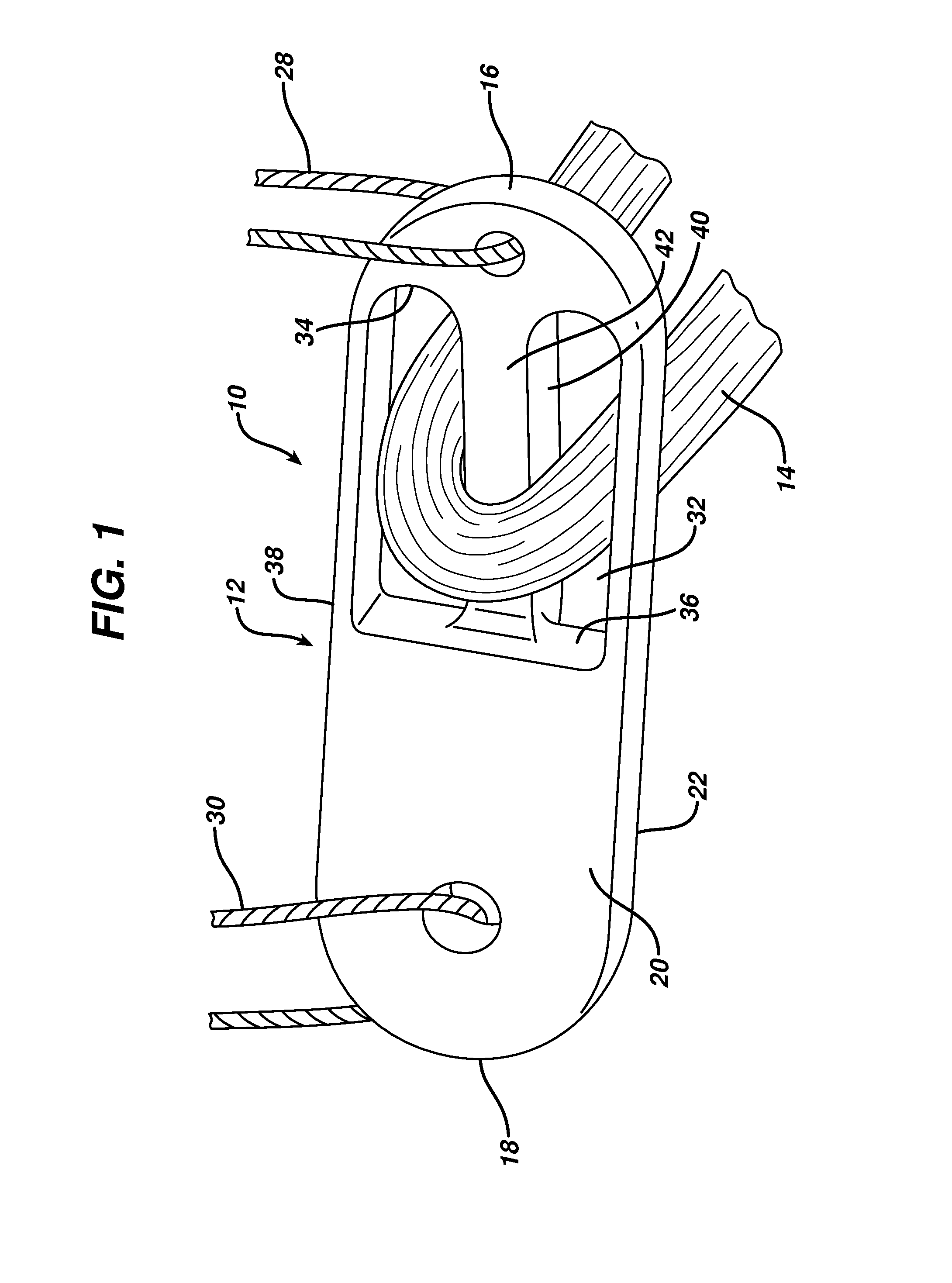
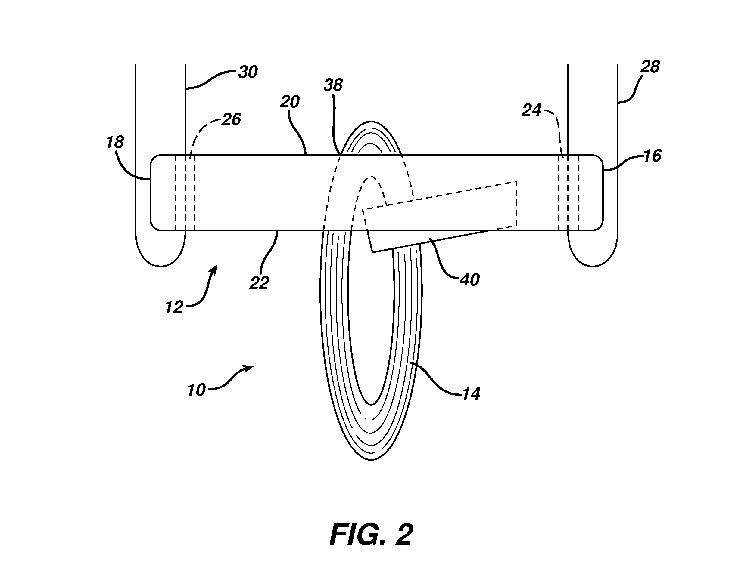
[0040]The gap which exists between the graft 46 and the end of the socket 54 can be reduced by the present invention. To evaluate this advantage similarly sized buckles were compared. Buckle A was a commercially available product similar to that described in the '301 Patent and Buckle B is the buckle 12 depicted in FIG. 1 herein. Each was 12.2 mm long, 4.0 mm wide, and 1.4 mm thick, with Buckle B being 2.5 mm thick at its midpoint due to the bottom of the tang depending below the lower surface. The buckles were threaded with loops of similar thickness and construction to each other; with the tests performed using loop lengths of between 15 and 30 mm. Caliper measurements were performed of the loop from the buckle to the furthest inside portion of the loop in two configurations: 1) the loop stretched downwardly from and perpendicular to the buckle as representative of the final fixation position, and 2) the loop stretched from the trailing end of the buckle and parallel to the buckle...
PUM
 Abstract
Description
Claims
Application Information