Apparatus for driving a plurality of segments of led-based lighting units

a technology for led-based lighting and apparatus, applied in lighting apparatus, electroluminescent light sources, light sources, etc., can solve the problems of reducing efficiency, costing more, and difficult to miniaturize led-based lighting devices, and achieve the effect of efficient driving

Inactive Publication Date: 2014-02-27
VASTVIEW TECH
View PDF5 Cites 4 Cited by
  • Summary
  • Abstract
  • Description
  • Claims
  • Application Information

AI Technical Summary

Benefits of technology

[0010]The present invention has been made to provide an apparatus that can efficiently drive an LED-based lighting apparatus to provide multiple operating modes according to the voltage level of an input AC voltage source. In accordance with the present invention, the LED-based lighting apparatus is divided into a plurality of LED-based lighting segments with each segment comprising a plurality of LED-based lighting units. The plurality of LED-based lighting segments are connected in series and the last segment is connected through a current control device to ground.
[0011]A primary object of the present invention is to provide an apparatus that can selectively turn on some or all the plurality of LED-based lighting segments as the input voltage level increases, and turn off some or all the LED-based lighting segments as the input voltage level decreases so as to provide multiple operating modes for the LED-based lighting apparatus.

Problems solved by technology

The need of a voltage conversion device reduces the efficiency, costs more and also makes it difficult to miniaturize an LED-based lighting device.

Method used


Image

  • Apparatus for driving a plurality of segments of led-based lighting units
  • Apparatus for driving a plurality of segments of led-based lighting units
  • Apparatus for driving a plurality of segments of led-based lighting units

Examples


first embodiment

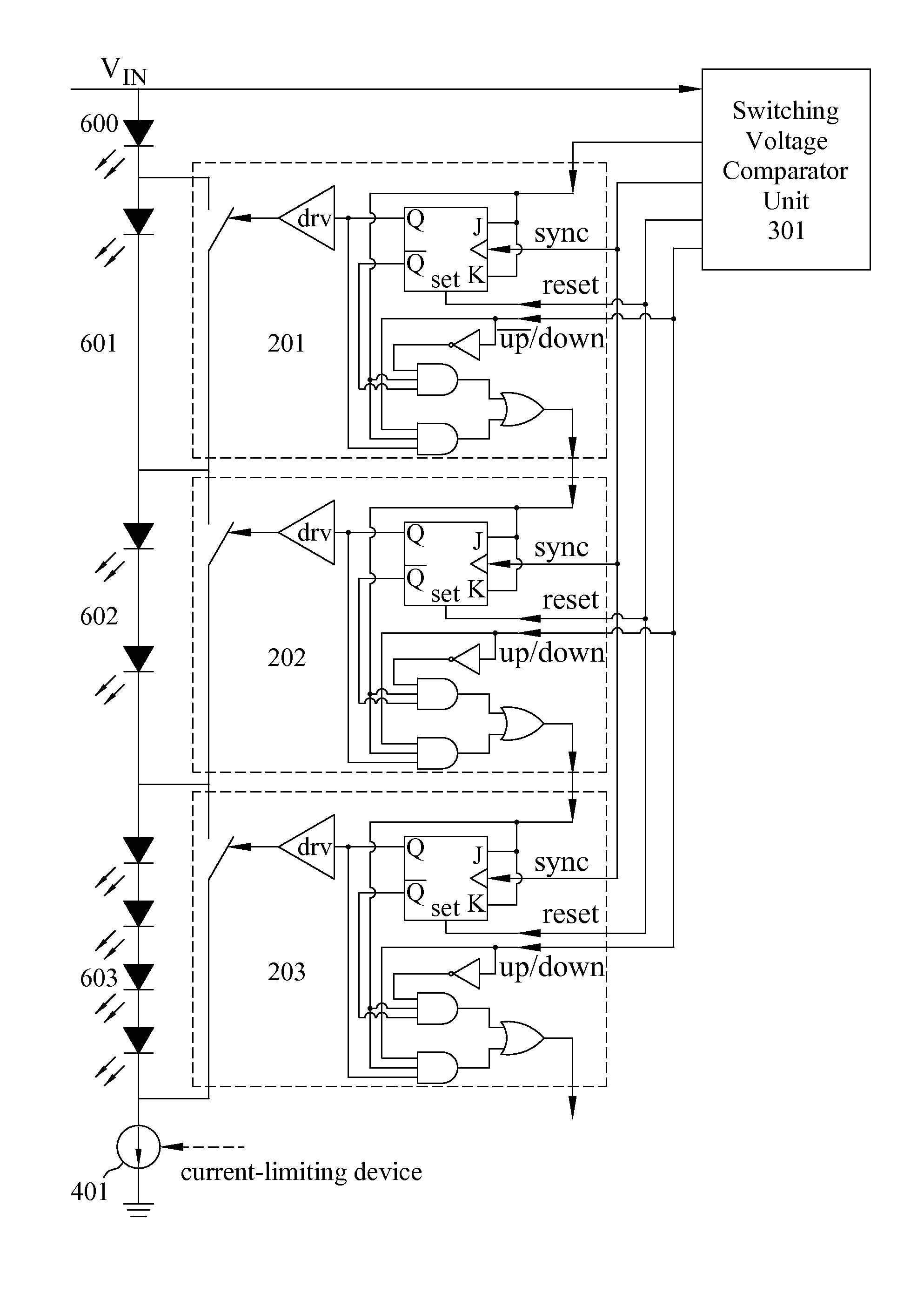
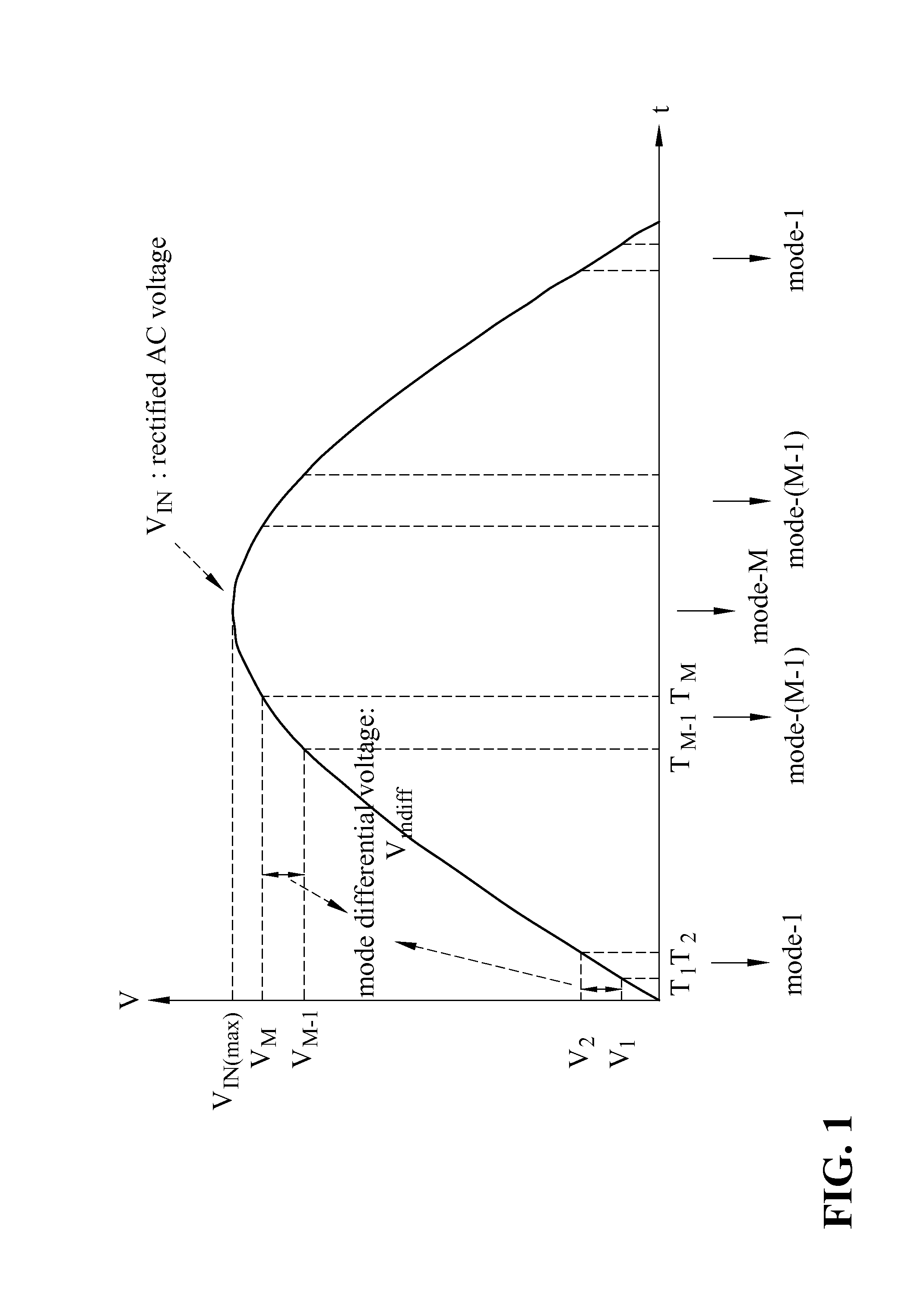
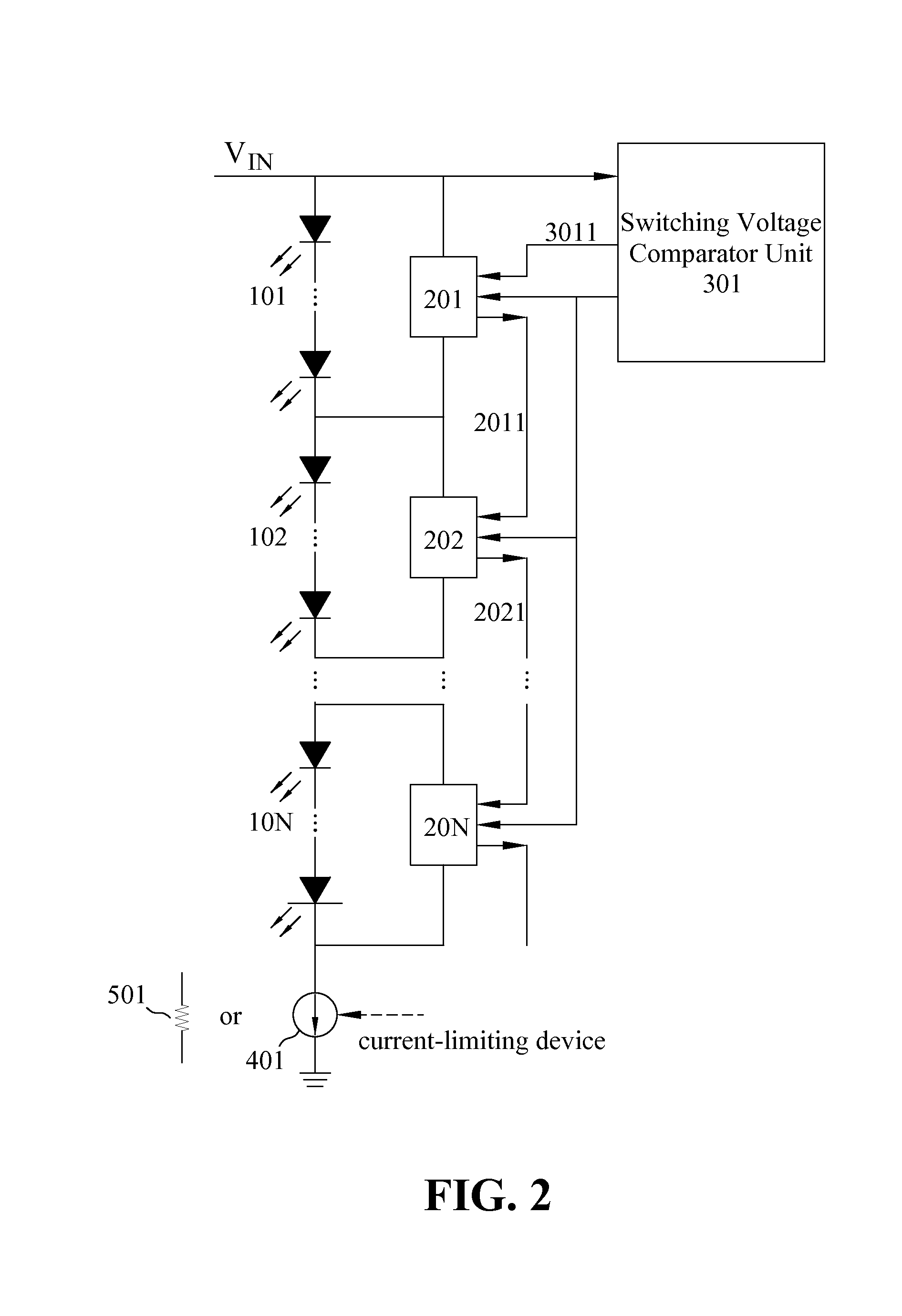
[0040]As shown in FIG. 1, the LED-based lighting apparatus of the present invention operates in Mode-i between time Ti and Ti+1 as the voltage level of the input voltage VIN increases between Vi and Vi+1. shown in FIG. 2, switch controllers 201, 202, . . . , 20N can be controlled by the switching voltage comparator unit 301 to selectively turn on the LED-based lighting units of one or more segments in LED-based lighting segments 101, 102, . . . , 10N.

[0041]As an example, during the period between time T1 and T2, switch controller 201 may be controlled by the switching voltage comparator unit 301 to turn on the LED-based lighting units in LED-based lighting segment 101 with all the other segments turned off, and switch controller 202 may be controlled to turn on the LED-based lighting segment 102 during the period between time T2 and T3 with all the other segments turned off. When the input voltage reaches the value between VM and VIN(Max), all the switch controllers 201, 202, . . ....

second embodiment

[0051]According to the present invention, each switch controller sends an output propagation signal to both its preceding and following switch controllers if they exist as shown in FIG. 7. Each switch controller also receives the output propagation signals sent from the preceding and following switch controllers if they are available. For example, switch controller 802 sends output propagation signal 8021 to both switch controller 801 and switch controller 803, and receives output propagation signal 8011 from switch controller 801 and output propagations signal 8031 from switch controller 803.

[0052]As can be seen in FIG. 7, the first switch controller 801 receives a first propagation signal 9011 from the switching voltage comparator unit 901 instead of a propagation signal from a preceding switch controller. In this embodiment, the last switch controller 80N receives a last propagation signal 9012 from the switching voltage comparator unit 901 instead of a propagation signal from a ...


PUM


Abstract

An LED-based lighting apparatus includes a plurality of LED-based lighting segments connected in series with a current control device. Each lighting segment has at least one LED-based lighting unit connected in series. A plurality of switch controllers controlled by a switching voltage comparator unit is connected with the plurality of LED-based lighting segments to provide multiple operation modes for turning on different number of LED-based lighting segments. In one embodiment, each switch controller is connected in parallel with a corresponding segment. The switching voltage comparator unit generates a propagation signal that propagates through and controls the plurality of switch controllers. In the other embodiment, each switch controller is connected between a positive end of the corresponding segment and a current control device. The switching voltage comparator unit generates two propagation signals that propagate through and control the plurality of switch controllers.

Description

BACKGROUND OF THE INVENTION[0001]1. Field of the Invention[0002]The present invention relates generally to LED-based lighting apparatuses, and more particularly to an apparatus for driving a plurality of LED-based lighting segments in an LED-based lighting apparatus.[0003]2. Description of Related Arts[0004]Light emitting diodes (LEDs) are semiconductor-based light sources often employed in low-power instrumentation and appliance applications for indication purposes. The application of LEDs in various lighting units has become more and more popular. For example, high brightness LEDs have been widely used for traffic lights, vehicle indicating lights, and braking lights.[0005]An LED has an I-V characteristic curve similar to an ordinary diode. When the voltage applied to the LED is less than a forward voltage, only very small current flows through the LED. When the voltage exceeds the forward voltage, the current increases sharply. The output luminous intensity of an LED light is app...

Claims


Application Information

Patent Timeline
Patent Type & Authority Applications(United States)
IPC IPC(8): H05B37/00H05B44/00
CPCH05B33/0824H05B33/0827H05B33/0815H05B37/00H05B33/083H05B33/0851H05B45/48H05B45/44H05B45/46
Inventor CHU, HUNG-CHISHEN, YUH-REN
Owner VASTVIEW TECH
Why Eureka
Try Eureka