Imaging apparatus

a technology of imaging apparatus and image, which is applied in the field of imaging apparatus, can solve the problems of difficult to obtain an appropriate recorded image and difficult to check a long exposure subject imag

Inactive Publication Date: 2014-11-13
FUJIFILM CORP
View PDF6 Cites 11 Cited by
  • Summary
  • Abstract
  • Description
  • Claims
  • Application Information

AI Technical Summary

Benefits of technology

[0026]According to the present invention, before the actual imaging of the long exposure imaging, it is possible to check the long exposure subject image through the...

Problems solved by technology

However, in a case where the imaging apparatus described in JP-2009-303258A or JP-2004-85935A performs long exposure imaging in a way of switching between the OVF and the EVF, when a subject image is viewed through the finder eye piece before the actual imaging, it is difficult to check a lo...

Method used


Image

  • Imaging apparatus
  • Imaging apparatus
  • Imaging apparatus

Examples


first embodiment

[0053]A first embodiment of the present invention will be described with reference to the drawings.

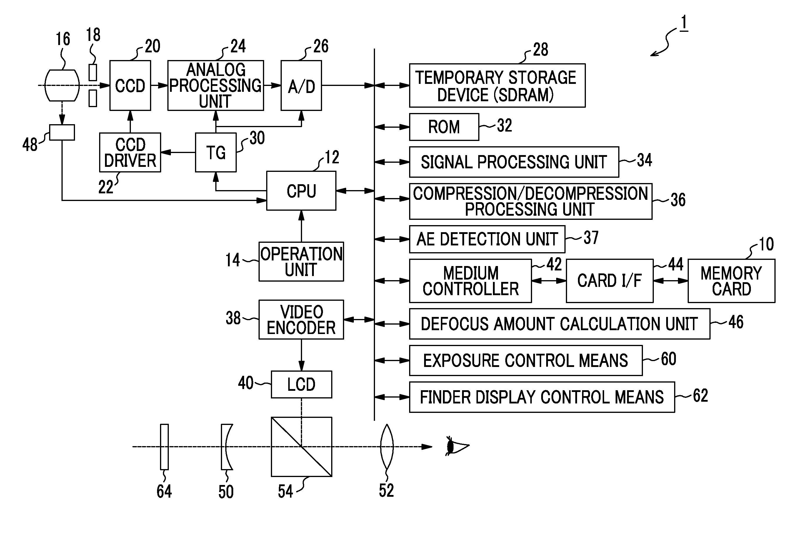
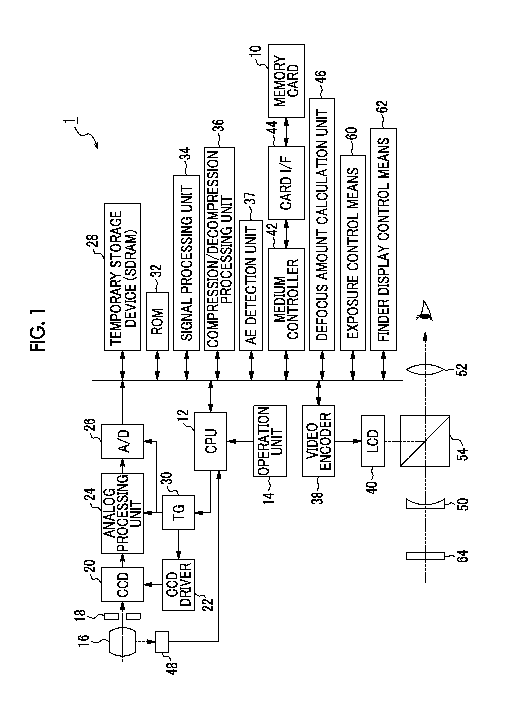
[0054]As shown in FIG. 1, the imaging apparatus 1 according to the present invention includes exposure control means 60 and finder display control means 62.

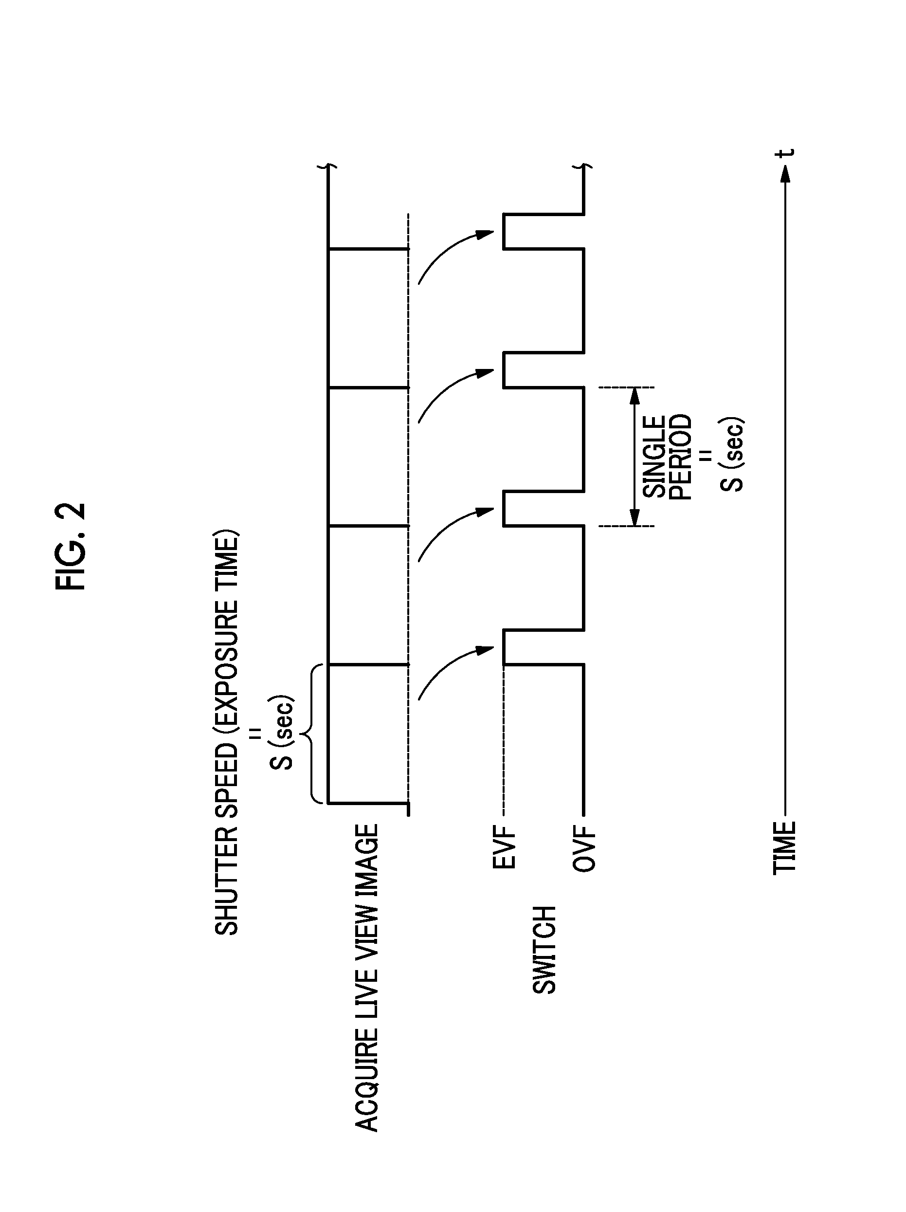
[0055]In the present invention, before the actual imaging of the long exposure imaging, the exposure control means 60 controls an exposure time of the live view image acquired by the CCD (imaging device) 20 such that the exposure time is the same as that in an actual imaging state. That is, by controlling the exposure time of the live view image acquired by the CCD 20 such that the exposure time is the same as that in the actual imaging state, it is possible to check the live view image through the eyepiece lens (eye piece) 52 of the finder. Thereby, a preview of the recorded image in the actual imaging state can be checked through the eyepiece lens 52 of the finder before the actual imaging of the long exposure imaging.

[0056]Howeve...

second embodiment

[0063]A second embodiment of the present invention will be described with reference to the drawings.

[0064]As shown in FIG. 1, the imaging apparatus 1 according to the present invention includes the exposure control means 60 and the finder display control means 62.

[0065]In the present invention, in a similar manner to the first embodiment, before the actual imaging of the long exposure imaging, the exposure control means 60 controls the exposure time of the live view image acquired by the CCD (imaging device) 20 such that the exposure time is the same as that in the actual imaging state. That is, by controlling the exposure time of the live view image acquired by the CCD (imaging device) 20 such that the exposure time is the same as that in the actual imaging state, it is possible to check the live view image through the eyepiece lens (eye piece) 52 of the finder. Thereby, a preview of the recorded image in the actual imaging state can be checked through the eyepiece lens 52 of the f...

third embodiment

[0070]As shown in FIG. 3, subject change detection means 66 is provided to the first and second embodiments. In addition, FIG. 3 selectively shows an EVF optical system 90 and an OVF optical system 92 of FIG. 1, and is a diagram in which the subject change detection means 66 is further provided to FIG. 1.

[0071]As described above, before the actual imaging of the long exposure imaging, the exposure control means 60 controls an exposure time of the live view image acquired by the CCD (imaging device) 20 such that the exposure time is the same as that in an actual imaging state. The subject image obtained from the CCD 20 is updated for every exposure time.

[0072]Consequently, by further providing the subject change detection means 66, the difference between the latest subject image and the previous subject image is detected. As a result, it is possible to detect the slight tilt of the imaging apparatus 1 or the big motion in the subject image.

[0073]Then, when the subject change detectio...


PUM


Abstract

The present invention provides an imaging apparatus configured such that it is possible to check a long exposure subject image through a finder eye piece before actual imaging of long exposure imaging so as to recognize a subtle change in the tilt of the imaging apparatus caused when the apparatus gradually tilts over a long time period. In the imaging apparatus of the present invention, exposure control means 60 controls an exposure time of a live view image, which is acquired by the imaging device 20, such that the exposure time is the same as that in the actual imaging, whereby it is possible to check the live view image from an eyepiece lens 52 of a finder.

Description

CROSS-REFERENCE TO RELATED APPLICATIONS[0001]This application is a Continuation of PCT International Application No. PCT / JP2013 / 054980 filed on Feb. 26, 2013, which claims priority under 35 U.S.C. §119(a) to Japanese Patent Application No. 2012-073117 filed Mar. 28, 2012. Each of the above application(s) is hereby expressly incorporated by reference, in its entirety, into the present application.BACKGROUND OF THE INVENTION[0002]1. Field of the Invention[0003]The present invention relates to an imaging apparatus, and particularly relates to an imaging apparatus that has an optical viewfinder and an electronic viewfinder and is capable of switching between the viewfinders.[0004]2. Description of the Related Art[0005]In the technical field of digital cameras (imaging apparatuses), until now, generally, an electronic image of a subject acquired by an imaging optical system of an imaging lens, an imaging device, and the like has been displayed on a liquid crystal monitor provided on the ...

Claims


Application Information

Patent Timeline
IPC IPC(8): H04N5/232G03B13/02H04N5/235
CPCH04N5/23293H04N5/2353G03B13/02G03B17/20G03B19/12H04N23/672H04N23/63H04N23/73G03B13/06G03B15/00
Inventor AOKI, TAKASHI
Owner FUJIFILM CORP
Why Eureka
Try Eureka