

Touch panel
- Summary
- Abstract
- Description
- Claims
- Application Information
AI Technical Summary
Benefits of technology
Problems solved by technology
Method used
Image

Examples
Embodiment Construction
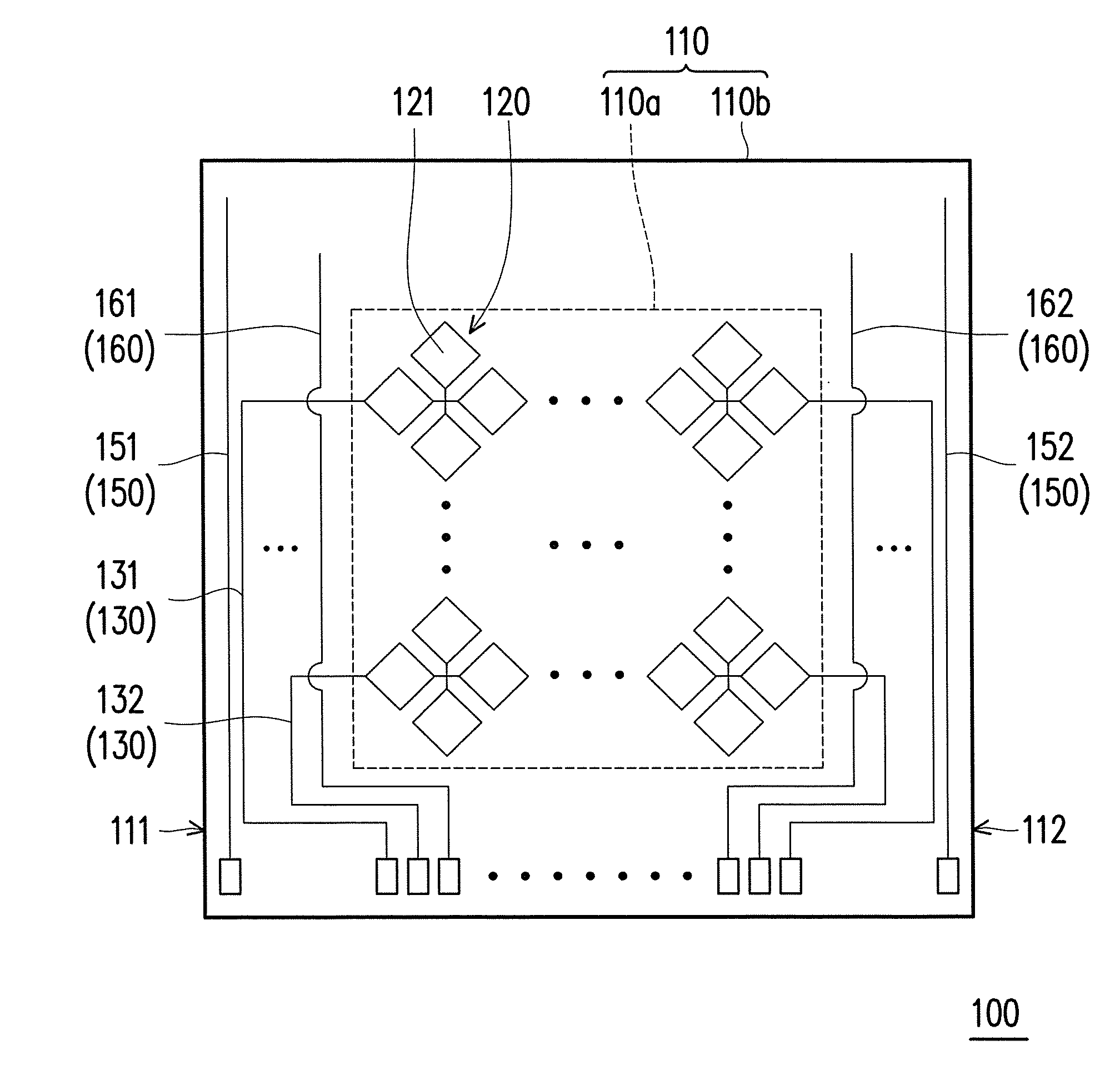
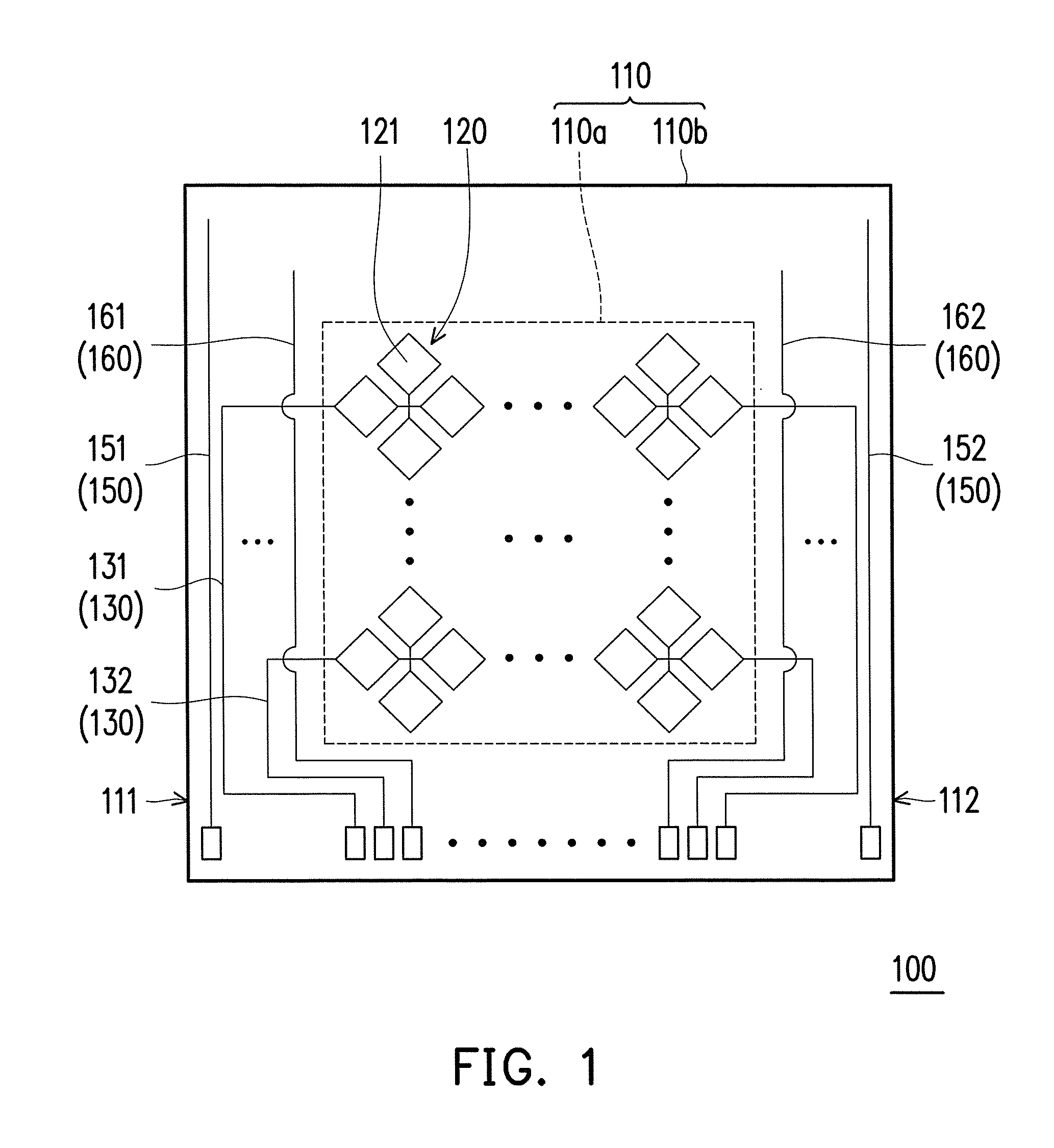
[0018]FIG. 1 is a schematic view illustrating a touch panel according to an embodiment of the invention. FIG. 2 is a schematic view illustrating local enlargement of the touch panel in FIG. 1. Please refer to both FIGS. 1 and 2. A touch panel 100 includes a substrate 110, a touch sensing array 120, a plurality of connecting lines 130, a plurality of extending portions 140, a first electrostatic discharge protection circuit 150 and a second electrostatic discharge protection circuit160. The substrate 110 is, for example, a glass substrate or a plastic substrate. The substrate 110 has an active region 110a and a periphery region 110b. The touch sensing array 120 is disposed in the active region 110a. The connecting lines 130 and extending portions 140 are disposed in the periphery region 110b. As shown in FIG. 1, in the embodiment, the extending portions 140 are arranged around the active region 110a, wherein an end of each of the connecting lines 130 is respectively connected to the ...
PUM
 Abstract
Description
Claims
Application Information