Head protection airbag apparatus

a technology for airbags and head protection, which is applied in the direction of vehicular safety arrangements, pedestrian/occupant safety arrangements, vehicle components, etc., can solve the problems of not being able to smoothly inflated airbags in some cases, and the lower edge side portion of the airbag interferes with a member, so as to suppress the interference and reduce the deployment.

Active Publication Date: 2015-04-30
TOYODA GOSEI CO LTD
View PDF11 Cites 8 Cited by
  • Summary
  • Abstract
  • Description
  • Claims
  • Application Information

AI Technical Summary

Benefits of technology

[0007]An object of the invention is to solve the above problem. There is provided a head protection airbag apparatus in which it is possible for an airbag to be smoothly deployed along a window and to be rapidly inflated, even in a case where the lower edge side of the fully inflated airbag is positioned lower than the belt line.
[0010]In the head protection airbag apparatus according to the present invention, the airbag is roll-folded to be wound toward the exterior side, after the lower edge side thereof is folded toward the interior or exterior side. The airbag is folded such that the lower edge-side end during the full inflation is disposed on the outermost circumferential side of the roll-folding portion that is wound toward the exterior side, that is, in a region where, when the roll-folding is released during deployment and inflation, the lower edge-side end is in a state of not following the inner circumferential portion of the roll-folding portion that is deployed on the inner circumferential side of the lower edge-side end, but being disposed at a position of the interior side of the inner circumferential portion. Therefore, the lower edge-side end is disposed such that the lower edge-side end does not follow the inner circumferential portion of the roll-folding portion that is deployed to be unfolded during an initial inflation of the airbag, but is deployed to release the folded state and to cover the interior side of the window, after the inner circumferential portion is substantially unfolded and deployed. As a result, in the head protection airbag apparatus according to the present invention, even though the airbag is folded by roll-folding to be wound toward the exterior side, and to position the lower edge-side end of the fully inflated airbag (the lower edge of the inflation shielding section) lower than the belt line that is composed of the lower edge of the window, it is possible to suppress interference between the lower edge side portion of the airbag and a member, such as a door trim that constitutes the belt line and protrudes to the interior side from the window using, when the roll-folding is released and the airbag is deployed. As a result, it is possible for the airbag to be rapidly deployed and to be smoothly inflated. In addition, in the head protection airbag apparatus according to the present invention, since the airbag is folded by roll-folding to be wound toward the exterior side, the airbag may be unfolded and deployed along the interior side of the window. Therefore, even in a case where a gap between the window and an occupant's head is narrow, it is possible for the airbag to be deployed to enter the narrow gap.
[0011]Thus, in the head protection airbag apparatus according to the present invention, even in a case where the lower edge side of the fully-inflated airbag is positioned lower than the belt line, it is possible for the airbag to be smoothly deployed along the window, and to be rapidly inflated.
[0013]In the head protection airbag apparatus having such a configuration, the lower edge-side end of the fully inflated airbag may be disposed at a position past the intersection point between the reference line that passes the upper edge at the time of the full inflation and the center of the roll-folding portion and the lower end side of the inner circumferential portion of the roll-folding portion that is deployed on the inner circumferential side of the lower edge-side end when the roll-folding is released during the deployment and inflation, on the outermost circumferential side of the roll-folding portion. Therefore, the lower edge-side end does not follow the inner circumferential portion of the roll-folding portion that is deployed to be unfolded during the initial inflation of the airbag, but may maintain a state in which the lower edge-side end is disposed to the interior side of the inner circumferential portion. After the inner circumferential portion is deployed while being substantially released from the folded state, the lower edge-side end is deployed to be released from the folded state and disposed to cover the interior side of the window. Therefore, in the head protection airbag apparatus having the configuration, even though the airbag is folded by roll-folding to be wound toward the exterior side, and is configured such that the lower edge-side end (the lower edge of the inflation shielding portion) of the fully inflated airbag is positioned lower than the belt line that is composed of the lower edge of the window, it is possible to suppress the interference between the lower edge side portion and a member, such as a door trim that configures the belt line and protrudes to the interior side from the window, when the roll-folding of the airbag is released and the airbag is deployed. As a result, it is possible for the airbag to be rapidly deployed and to be smoothly inflated. In addition, in the head protection airbag apparatus having the configuration, since the airbag is folded by the roll-folding to be wound toward the exterior side, the airbag is deployed while being released from the folded state along the interior side of the window. Therefore, even in a case where the gap between the window and the occupant's head is narrow, it is possible to deploy the airbag to enter the narrow gap.
[0014]Therefore, in the head protection airbag apparatus having the above-described configuration, even in a case where the lower edge side of the fully inflated airbag is positioned lower than the belt line, it is possible for the airbag to be smoothly deployed along the window and to be rapidly inflated.
[0018]When the head protection airbag apparatus has the above-described configuration, it is possible to still more reliably suppress the deployment of the lower edge-side end by following the releasing of the inner circumferential portion of the roll-folding portion. In addition, since the interior side of the lower edge-side end is covered by the bellows-folding portion, and is not exposed, it is possible to suppress the interference between the lower edge-side end with a member, such as a roof head lining, when the airbag is mounted on the vehicle.

Problems solved by technology

However, when such a configuration is applied to an airbag that has a configuration in which the lower edge side of the fully inflated airbag is positioned lower than a belt line which is composed of the lower edge of the window, a problem arises as follows.
In a case of the airbag having such a configuration, when the roll-folding of the airbag is released and the airbag is deployed, the lower edge side portion interferes with a member, such as a door trim that constitutes the belt line and protrudes to the interior side from the window.
Thus, it is not possible for the airbag to be smoothly inflated in some cases.

Method used


Image

  • Head protection airbag apparatus
  • Head protection airbag apparatus
  • Head protection airbag apparatus

Examples


Embodiment Construction

[0027]Preferred embodiments of the present invention are described below with reference to the accompanying drawings. However, the invention is not limited to the embodiments disclosed herein. All modifications within the appended claims and equivalents relative thereto are intended to be encompassed in the scope of the claims.

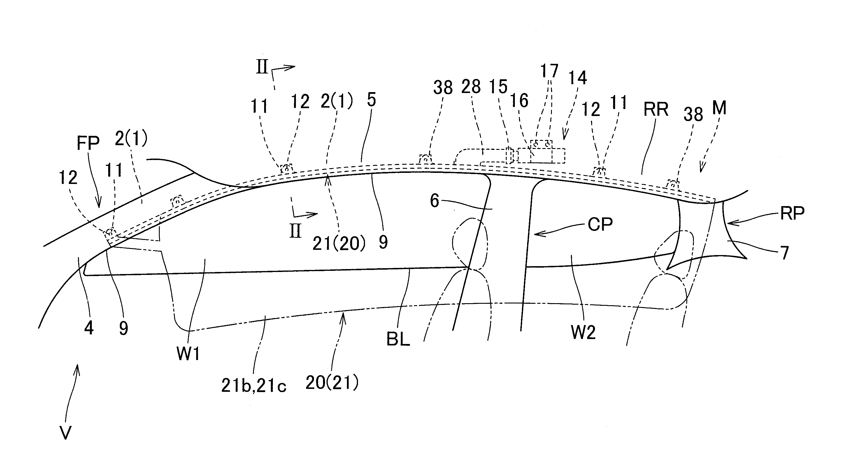
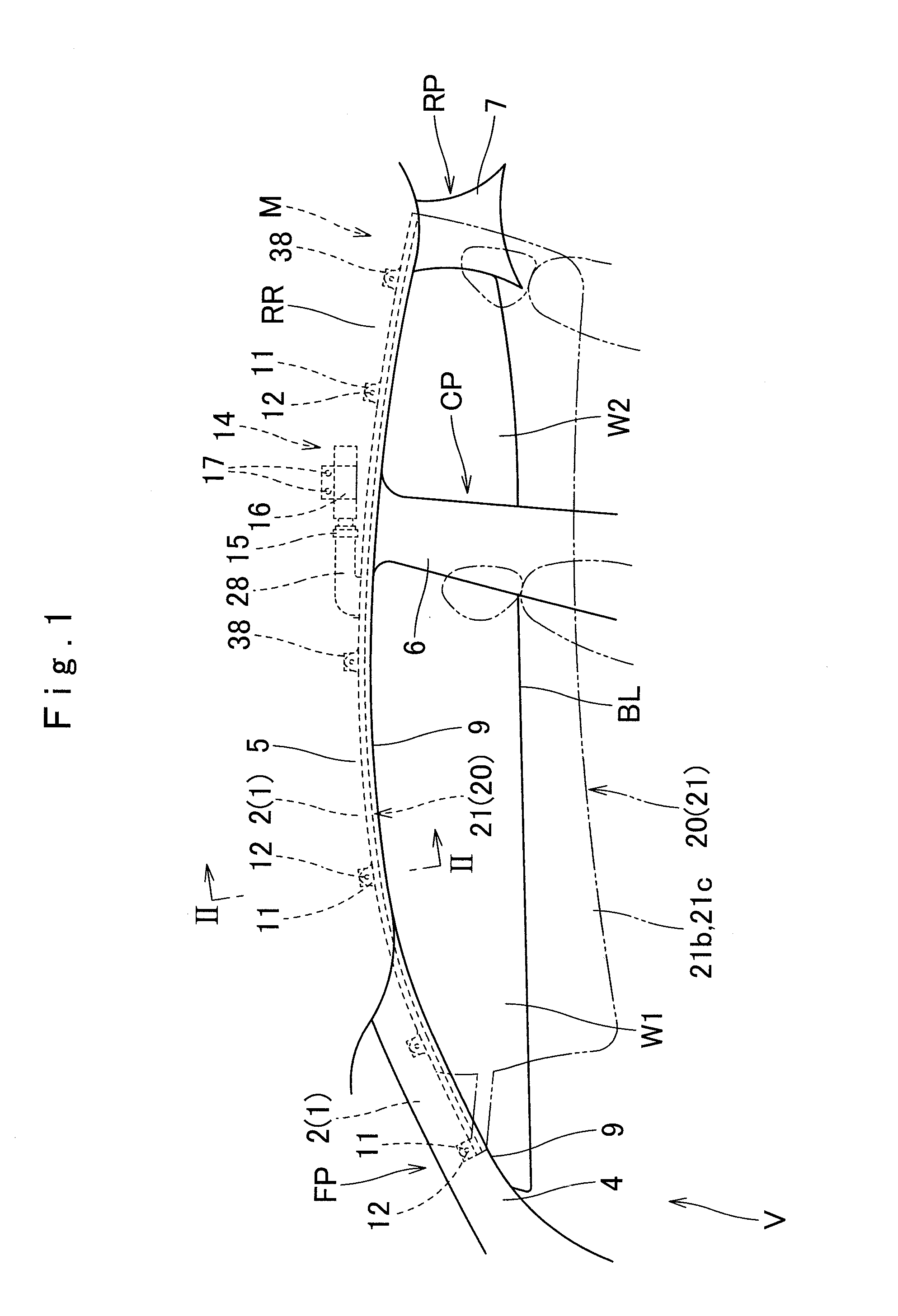
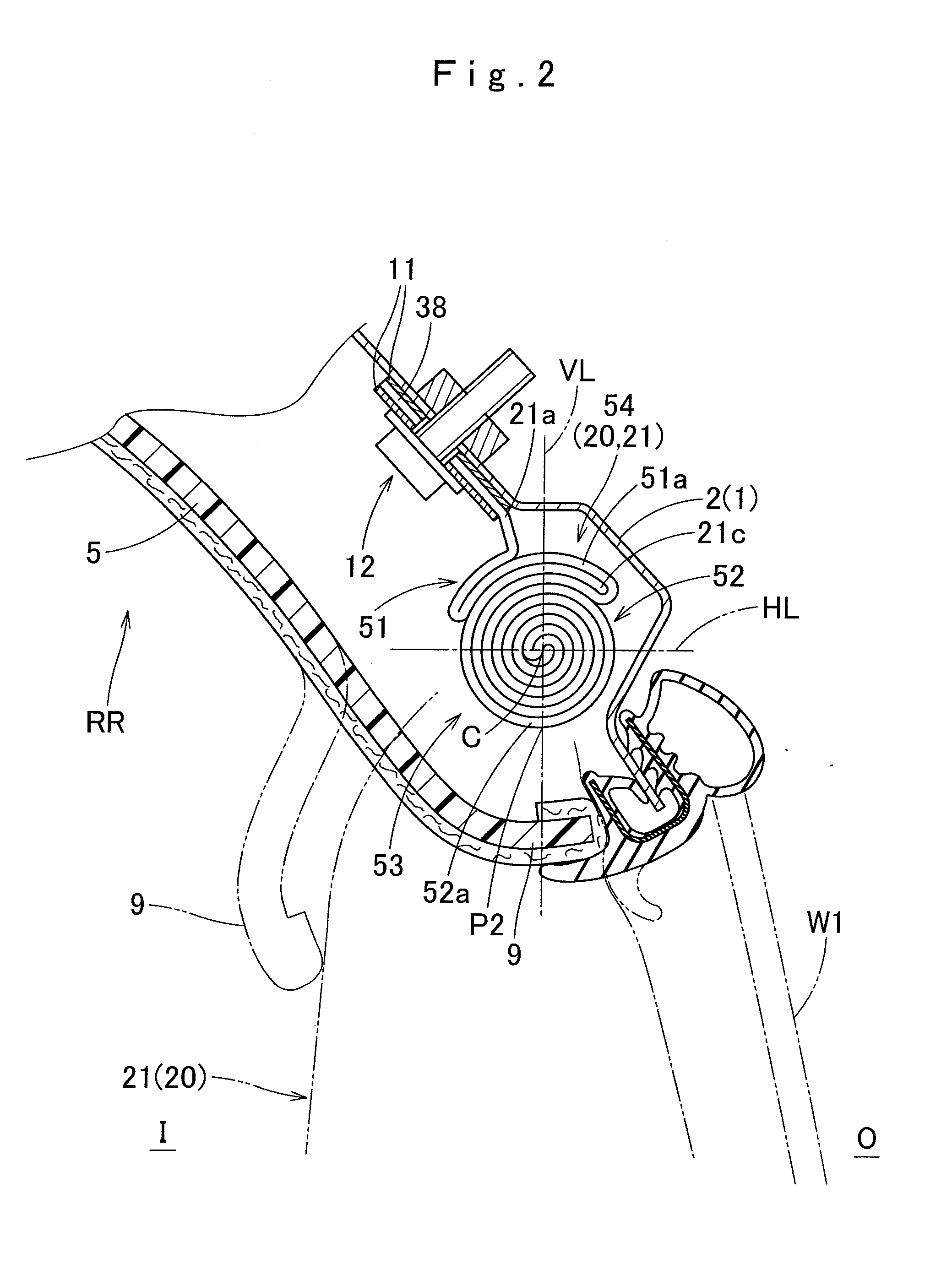
[0028]Hereinafter, an embodiment of the invention will be described with reference to the drawings. As shown in FIG. 1, a head protection airbag apparatus M according to the embodiment is mounted on a two-row seat type vehicle V that includes two windows (side windows) W1 and W2. The head protection airbag apparatus M according to the embodiment includes an airbag 20, an inflator 14, attachment brackets 11 and 16, and an airbag cover 9. The airbag 20 is folded and accommodated on the upper edge side of the windows W1 and W2 on the interior side of the vehicle V, as shown in FIG. 1. Specifically, as shown in FIG. 1, the folded airbag 20 is accommodated in a reg...


PUM


Abstract

An airbag has a configuration in which the lower edge of the inflation shielding section is positioned lower than a belt line that is composed of the lower edge of the window at the time of the full inflation. The airbag is roll-folded such that the lower edge side thereof is wound toward the exterior side after the lower edge side thereof is folded to the exterior side, and is folded such that the lower edge-side end at the time of the full inflation is positioned on the outermost circumferential side of a roll-folding portion. The airbag is folded such that the lower edge-sided end is disposed in a region where, when the roll-folding is released during deployment and inflation, the lower edge-side end does not follow the inner circumferential portion of the roll-folding portion that is deployed on the inner circumferential side of the lower edge-side end, but is disposed at a position of the interior side of the inner circumferential portion.

Description

CROSS REFERENCE TO RELATED APPLICATIONS[0001]The Present application claims priority from Japanese Patent Application No, 2013-225696 of Ikenohata, filed on Oct. 30, 2013, the disclosure of which is hereby incorporated into the present application by reference.BACKGROUND OF THE INVENTION[0002]1. Field of the Invention[0003]The present invention relates to a head protection airbag apparatus that includes an airbag which is folded and accommodated on the upper edge side of the interior side of a window, and to attach the upper edge side at the time of a full inflation to the body side of a vehicle, in which the lower edge side of the airbag at the time of the full inflation is positioned lower than a belt line that is composed of the lower edge of the window.[0004]2. Description of Related Art[0005]In the related art, there is a head protection airbag apparatus that has a configuration disclosed in JP-A-2004-114829. In the head protection airbag apparatus of the related art, an airbag...

Claims


Application Information

Patent Timeline
Patent Type & Authority Applications(United States)
IPC IPC(8): B60R21/237B60R21/232
CPCB60R21/237B60R2021/0048B60R21/232
Inventor IKENOHATA, SHO
Owner TOYODA GOSEI CO LTD
Why Eureka
Try Eureka