Stereoscopic image display device

Active Publication Date: 2015-06-25
SHANGHAI TIANMA MICRO ELECTRONICS CO LTD +1
View PDF3 Cites 8 Cited by
  • Summary
  • Abstract
  • Description
  • Claims
  • Application Information

AI Technical Summary

Benefits of technology

[0009]In view of this, the disclosure provides a new stereoscopic image display device. The stereoscopic image display device includes a plurality of display units arranged in rows and columns, a first black matrix is disposed between adjacent rows of display units, and a second black matrix is disposed between adjacent columns of display units. The stereoscopic image display device further includes a lens sheet disposed corresponding to the plurality of display units. The l

Problems solved by technology

However, a conventional stereoscopic image display device formed by a lens structure and a 2D displayer has the problem of uneven display, such as the occurrence of black and whit

Method used


Image

  • Stereoscopic image display device
  • Stereoscopic image display device
  • Stereoscopic image display device

Examples


first embodiment

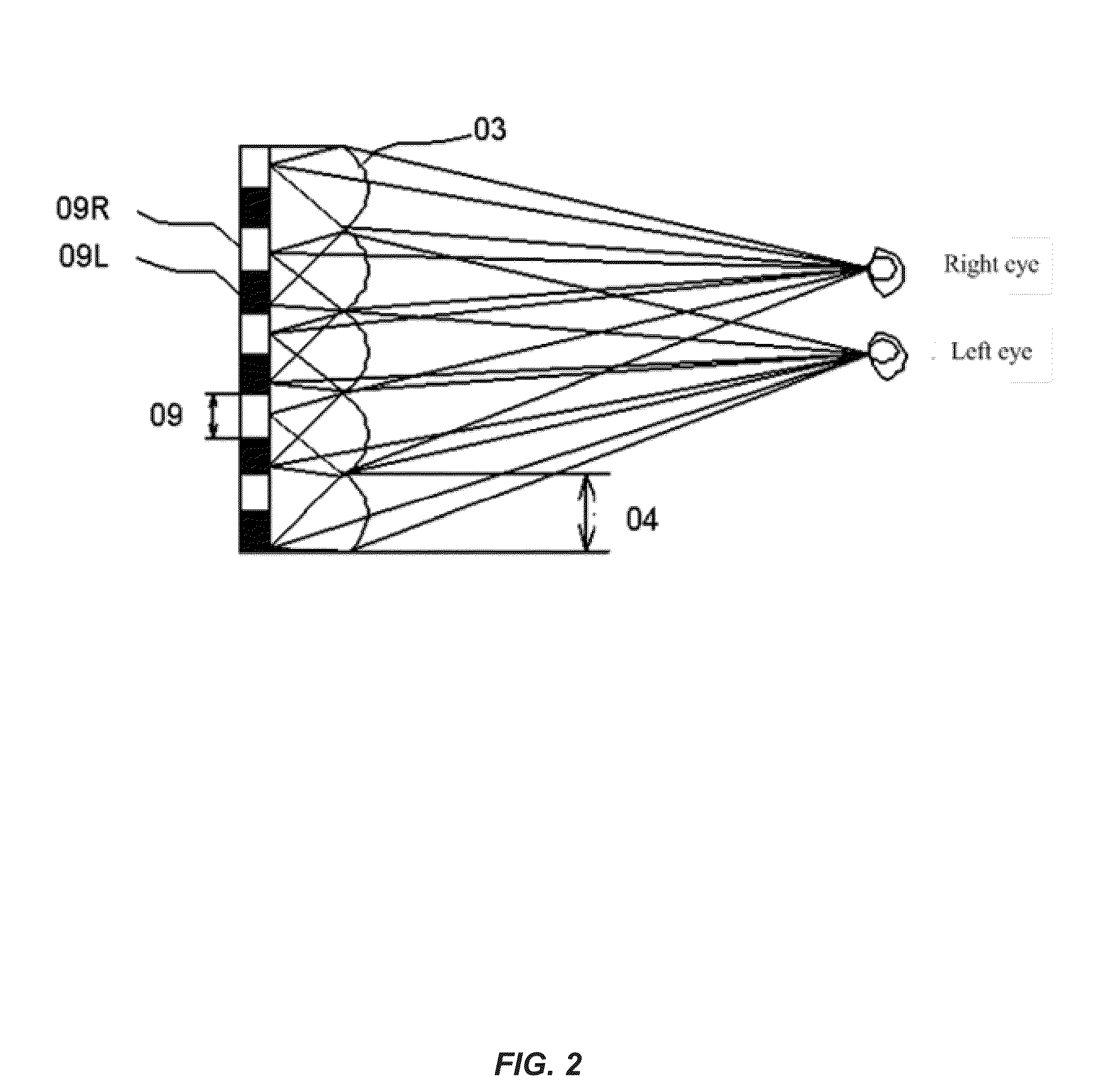
[0030]In the X-direction, the length of one cycle of the lens sheet 13, i.e., the length of one half-cylinder lens 14, is a positive even multiple of the length of one cycle of the pixel units 10. In the first embodiment, the length of the half-cylinder lens 14 is twice of the length of one cycle of the pixel units 10, that is, one half-cylinder lens 14 corresponds to two columns of pixel units 10, where the two columns of pixel units 10 are a left pixel L for providing an image to be observed by the left eye and a right pixel R for providing an image to be observed by the right eye, respectively. When the eyes observe at the observation point, lights from the pixel unit 10 are refracted by the lens sheet 13 in a way that the light from the right pixel R only arrives at the right eye and the light from the left pixel L only arrives at the left eye, and then these lights are converged stereoscopically via the human visual center to obtain stereoscopic sensation.

[0031]Within one cycle...

second embodiment

[0039]For convenience of design and calculation, the second embodiment provides a stereoscopic image display device in which an offset of the X coordinate value of each pixel unit in a column of pixel units with respect to the X coordinate value of a first pixel unit in the column does not exceed the length M of the pixel unit in the X-direction. That is, in one column of pixel units, if the minimum X coordinate value of the pixel unit is Xa and the maximum X coordinate value of the pixel unit is Xb, then 0b−Xa

[0040]For the above stereoscopic image display device, after the X coordinate values of the pixel units in one column are calculated, the X coordinate values of the pixel units in a next column may be obtained by adding M to the X coordinate values of the pixel units in the previous column respectively. In one column of pixel units, an offset of the X coordinate value of each pixel unit with respect to the X coordinate value of the first pixel unit in the column does not ex...

third embodiment

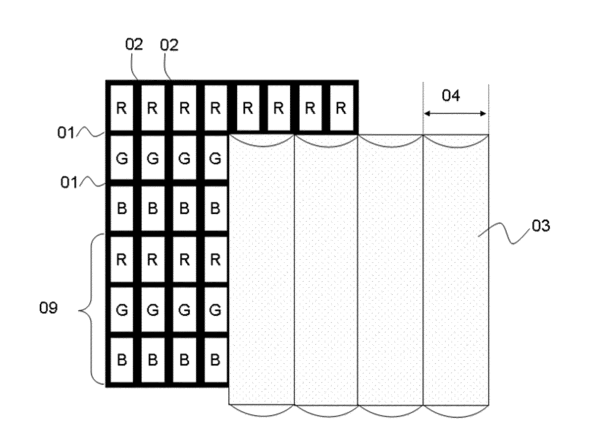
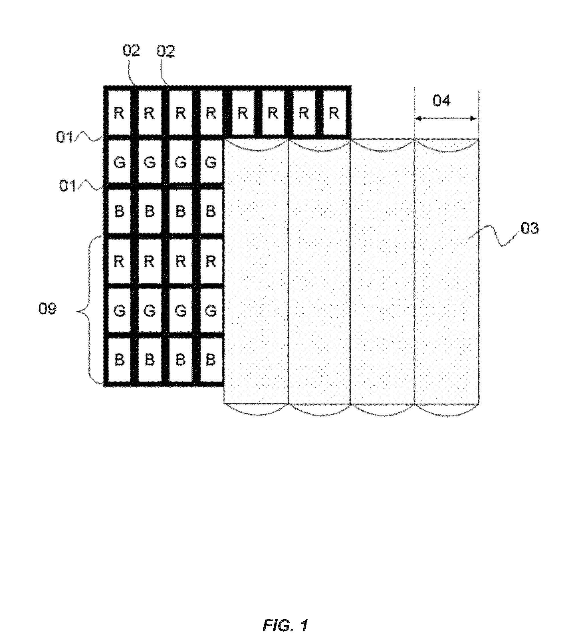
[0076]The color sub-pixel units 30 in one row have a same color, and the rows of color sub-pixel units that have different colors are alternatively arranged. In the third embodiment, the row of red (R) sub-pixel units, the row of green (G) sub-pixel units and the row of blue (B) sub-pixel units are alternatively arranged. Three adjacent color sub-pixel units 30 in the vertical direction, which have different colors, form one pixel unit 39. As shown in FIG. 8, one pixel unit 39 includes a R sub-pixel unit, a G sub-pixel unit and a B sub-pixel unit which are adjacent.

[0077]The stereoscopic image display device further includes a lens sheet 33 disposed corresponding to the multiple pixel units 39. The lens sheet 33 is formed by multiple lined up half-cylinder lenses. The lens sheet 33 is disposed between an observation point and the multiple pixel units 39. In the X-direction, a cycle length 34 of the half-cylinder lenses in the lens sheet is a positive even multiple of a cycle length ...


PUM


Abstract

The disclosure provides a stereoscopic image display device, including: multiple display units, the multiple display units being arranged in rows and columns, a first black matrix being disposed between adjacent rows of display units, and a second black matrix being disposed between adjacent columns of display units. The stereoscopic image display device also includes a lens sheet disposed corresponding to the multiple display units, the lens sheet being formed by multiple lined up half-cylinder lenses, and, in an X-direction, a cycle length of the half-cylinder lenses in the lens sheet being a positive even multiple of a cycle length of the display units. In the display device, X coordinate values of the multiple display units do not repeat periodically within one cycle of the lens sheet. The stereoscopic image display device according to the disclosure can solve a problem of black and white stripes, thereby improving the display effect.

Description

CROSS-REFERENCES TO RELATED APPLICATIONS[0001]This application claims the benefit of priority to Chinese Patent Application No. 201310703489.4, filed with the Chinese Patent Office on Dec. 19, 2013 and entitled “STEREOSCOPIC IMAGE DISPLAY DEVICE”, the content of which is incorporated herein by reference in its entirety.FIELD OF THE INVENTION[0002]The disclosure relates to the stereoscopic display field, and particularly to a stereoscopic image display device with improved display effect.BACKGROUND OF THE INVENTION[0003]The basic principle of the stereoscopic display technology is that, with parallax between human's right and left eyes, a display picture is provided to the left eye and the right eye respectively as a left picture and a right picture, and then the left picture and the right picture are mixed into a stereoscopic picture in the brain of an observer.[0004]Conventionally, the stereoscopic display is mainly achieved by means of convex lens technology. However, a convention...

Claims


Application Information

Patent Timeline
IPC IPC(8): H04N13/04G02B30/29
CPCH04N13/0404H04N13/257H04N13/305G02B30/29G02B30/27
Inventor NIU, LEITAO, YUHONGWU, ZHANGBENLING, ZHIHUA
Owner SHANGHAI TIANMA MICRO ELECTRONICS CO LTD
Why Eureka
Try Eureka