Slide valve for a ventilation device

a technology of sliding valve and ventilation device, which is applied in ventilation systems, lighting and heating apparatus, heating types, etc., can solve the problems of unfavorable installation, unfavorable installation, and unfavorable installation, and achieve the effect of convenient installation

Inactive Publication Date: 2015-09-03
SWEGON AB
View PDF15 Cites 6 Cited by
  • Summary
  • Abstract
  • Description
  • Claims
  • Application Information

AI Technical Summary

Benefits of technology

[0006]The object of the present invention is to provide a slide valve and a valve device in a ventilation install...

Problems solved by technology

Leakage leads to unnecessary ventilation and thus energy waste.
Leakage may also lead to the occurrence of undesired noise in...

Method used


Image

  • Slide valve for a ventilation device
  • Slide valve for a ventilation device

Examples


Embodiment Construction

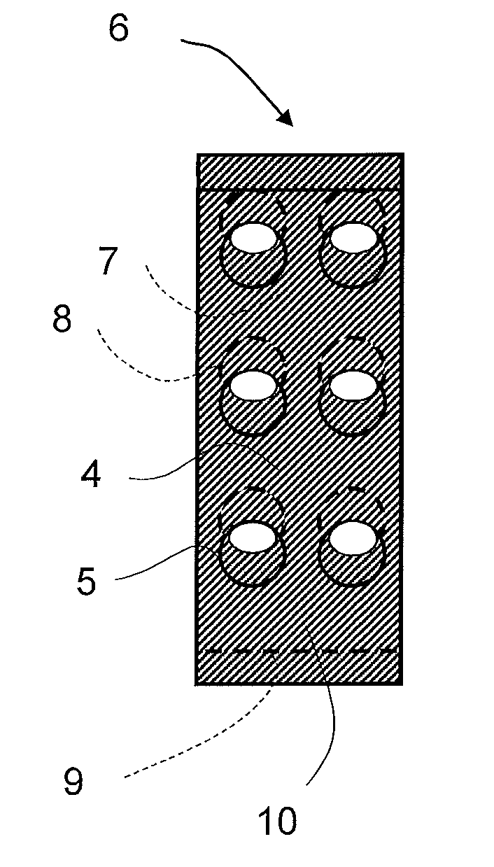
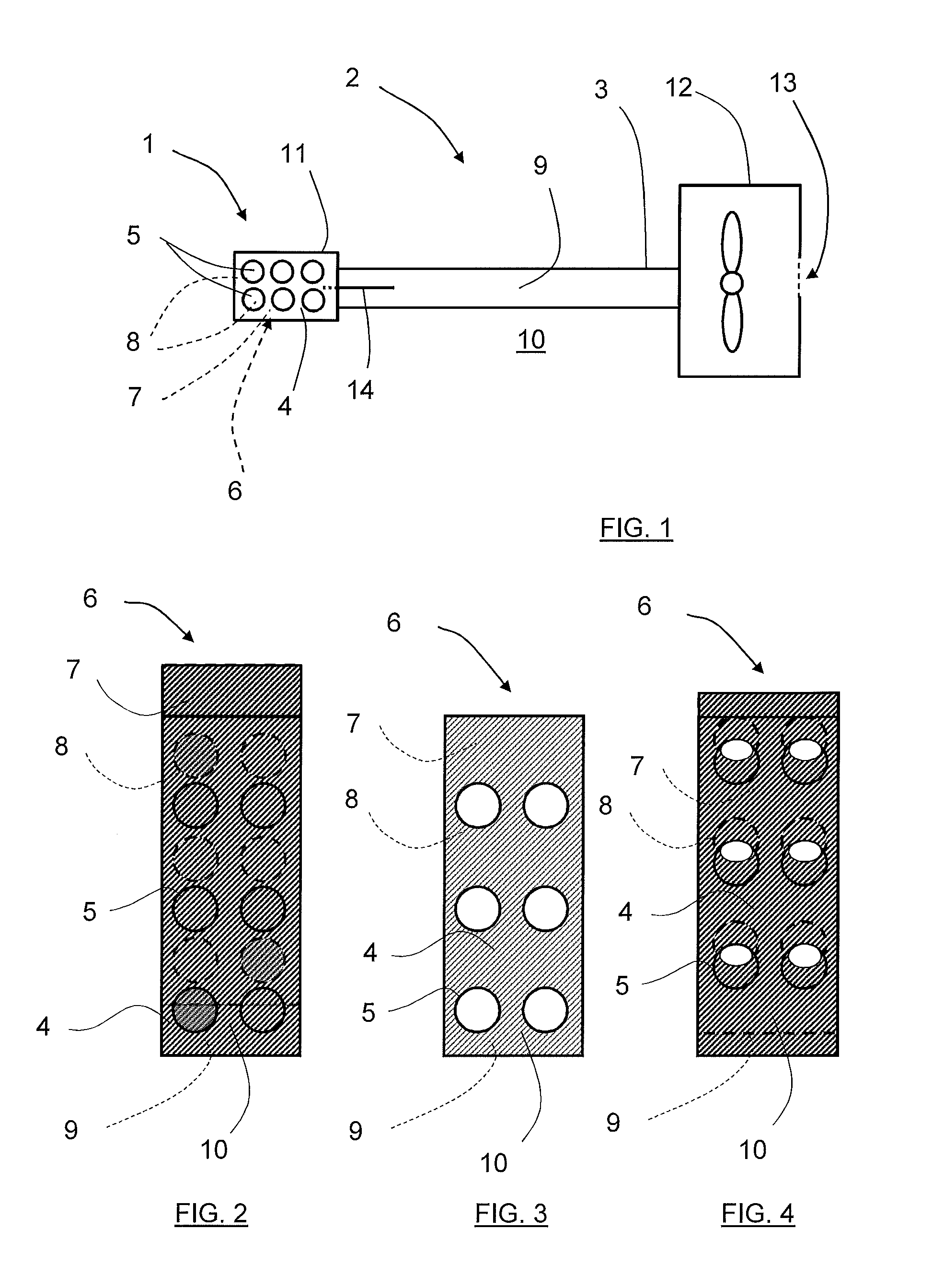
[0022]FIG. 1 shows a schematic view of a piece of ventilation installation 2 with a valve device 1 comprised in a supply air diffusor 11 at the end of a duct 3. The figure thus shows a very simple ventilation installation 2 and it is possible to add more supply air diffusors 11 and ducts to the installation 2. The ventilation arrangement is shown viewed from below. The duct 3 is connected to a fan 12 that is used to create an air flow by sucking in fresh air 13 and distributes in the duct such that a high pressure side 9 is created in the duct that has a higher pressure than what is present in the surrounding air outside the duct, the low pressure side 10. The valve device 1 comprises a vent surface 4 in the duct 3 which has been made by making a plurality of vent apertures 5 for passage of air in the duct 3 such that a supply air diffusor 11 has been created. The vent surface 4 is intended to co-operate with a slide valve 6 (see FIG. 2) which is attached to a drawing arm 14.

[0023]F...


PUM


Abstract

The present invention relates to a valve device (1) for a ventilation installation. The valve device (1) comprises a vent surface (4) that is equipped with a plurality of vent apertures (5) and a slide valve (6) comprising a slide valve plate (7) equipped with a plurality of slide valve apertures (8). The valve plate formed such that it can be varied between taking a first position (I) at which the vent apertures (5) are covered by the slide valve plate (7), and taking a second position (II) at which at least some vent apertures (5) have surfaces that overlap with some slide valve apertures (8) such that an air flow is permitted through the valve device (1). The valve device (1) is designed such that when the slide valve plate (7) is positioned on that side of the vent surface (4) that normally has a relatively higher pressure, the high pressure side (9), than the other side, the low pressure side (10). The slide valve plate (7) is formed such that the force from the pressure difference between the high pressure side (9) and the low pressure side (10) is sufficient to retain the slide valve plate in its place at the vent surface (4) when it is in the first, closed position (I).

Description

TECHNICAL FIELD[0001]The present invention relates to a valve device and a slide valve for a ventilation installation.BACKGROUND[0002]During ventilation fresh air is in many cases supplied via supply air diffusors, it may be one or more that are connected to a main pipe, where supplied fresh air is brought into motion towards the supply air diffusors via the main pipe by means of a fan arrangement. A supply air diffusor may in its least complicated form be an opening or aperture in the ventilation system. The supply air diffusor may also be integrated with a cooling or heating baffle to be able to control the temperature of the supplied air. The supply air diffusor may in these cases be arranged such that the fresh air that is supplied to the room brings existing air in the room such that is passes a heat exchanger in a cooling / heating baffle and is tempered.[0003]It is sometimes desirable to control the flow of supplied air in dependence of the present need. For example, a conferen...

Claims


Application Information

Patent Timeline
IPC IPC(8): F24F13/12
CPCF24F13/12F24F7/065F24F13/16F24F13/06F24F11/74
Inventor SODERBERG, TOMASLARSSON, PER- KE
Owner SWEGON AB
Why Eureka
Try Eureka