Fuel supply apparatus

a technology of fuel supply and fuel tank, which is applied in the direction of liquid fuel feeders, machines/engines, transportation and packaging, etc., can solve the problems of inability to reduce the supply of fuel is unlikely to be flowed smoothly, and the vapor generated in the fuel tank may not smoothly circulate through the breather port to the fuel tank, etc., to suppress the increase in the internal pressure of the fuel tank, smooth flow, and suppress turbulen

Active Publication Date: 2016-09-22
TOYODA GOSEI CO LTD +1
View PDF8 Cites 11 Cited by
  • Summary
  • Abstract
  • Description
  • Claims
  • Application Information

AI Technical Summary

Benefits of technology

[0018]According to one aspect of the invention, the rib serves to divide the flow of the fuel vapor. This enables the fuel vapor to be smoothly flowed inside of the fuel supply apparatus with suppressing turbulence from being generated in the fuel vapor in the middle of circulation. This accordingly suppresses an increase in internal pressure of the fuel tank and enables the fuel supplied from the fueling nozzle to be smoothly flowed into the fuel tank. Rectifying the fuel vapor by the rib enables the fuel vapor to be smoothly joined with the fuel. This enables the fuel vapor to be smoothly joined with the fuel without causing turbulence and improves the fueling performance of the fuel supplied from the fueling nozzle. This configuration also causes the fuel vapor introduced to downstream by the guide portion to be diffused in the outer circumferential space. This suppresses accumulation of the fuel vapor and suppresses turbulence of the fuel vapor.
[0019]According to another aspect of the invention, the nozzle guide has the enlarged opening portion that is wide open in the circumferential direction. Even in the case of rotation of the fueling nozzle inserted in the fuel supply apparatus, this configuration enables the gas sensor for the fueling nozzle to quickly detect the liquid level of the fuel supplied to the fuel supply apparatus at the predetermined position.

Problems solved by technology

In the fuel supply apparatuses described in JP 2009-83569A and in JP 2010-195062A, the fuel vapor generated in the fuel tank may not smoothly circulate through the breather port to the fuel tank and may thus fail to reduce the internal pressure of the fuel tank.
In this case, the supplied fuel is unlikely to be flowed smoothly by the internal pressure of the fuel tank as the resistance.
This may lead to poor fueling performance that does not allow the circulated fuel vapor to be smoothly joined with the supplied fuel and thereby fails to achieve smooth fueling.
There is, however, a possibility that some positional relationship of the gas sensor provided on the fueling nozzle to the nozzle guide of the fuel supply apparatus in which the fueling nozzle is inserted detects the fuel supplied to the fuel supply apparatus with some delay and causes the fuel to be overflowed from the fuel supply apparatus.

Method used


Image

  • Fuel supply apparatus
  • Fuel supply apparatus
  • Fuel supply apparatus

Examples


Embodiment Construction

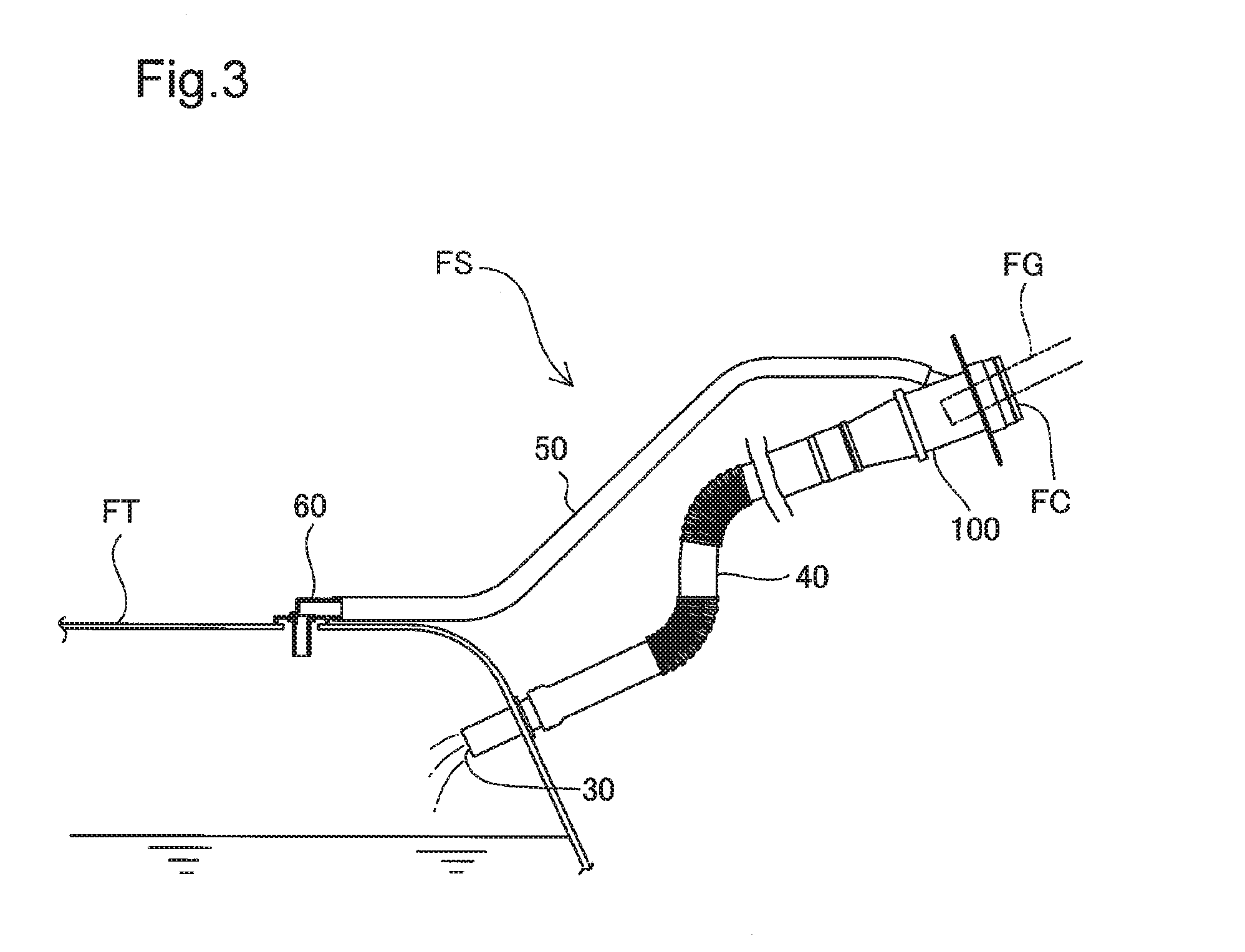
[0038](1) General Configuration of Fuel Supply Apparatus FS

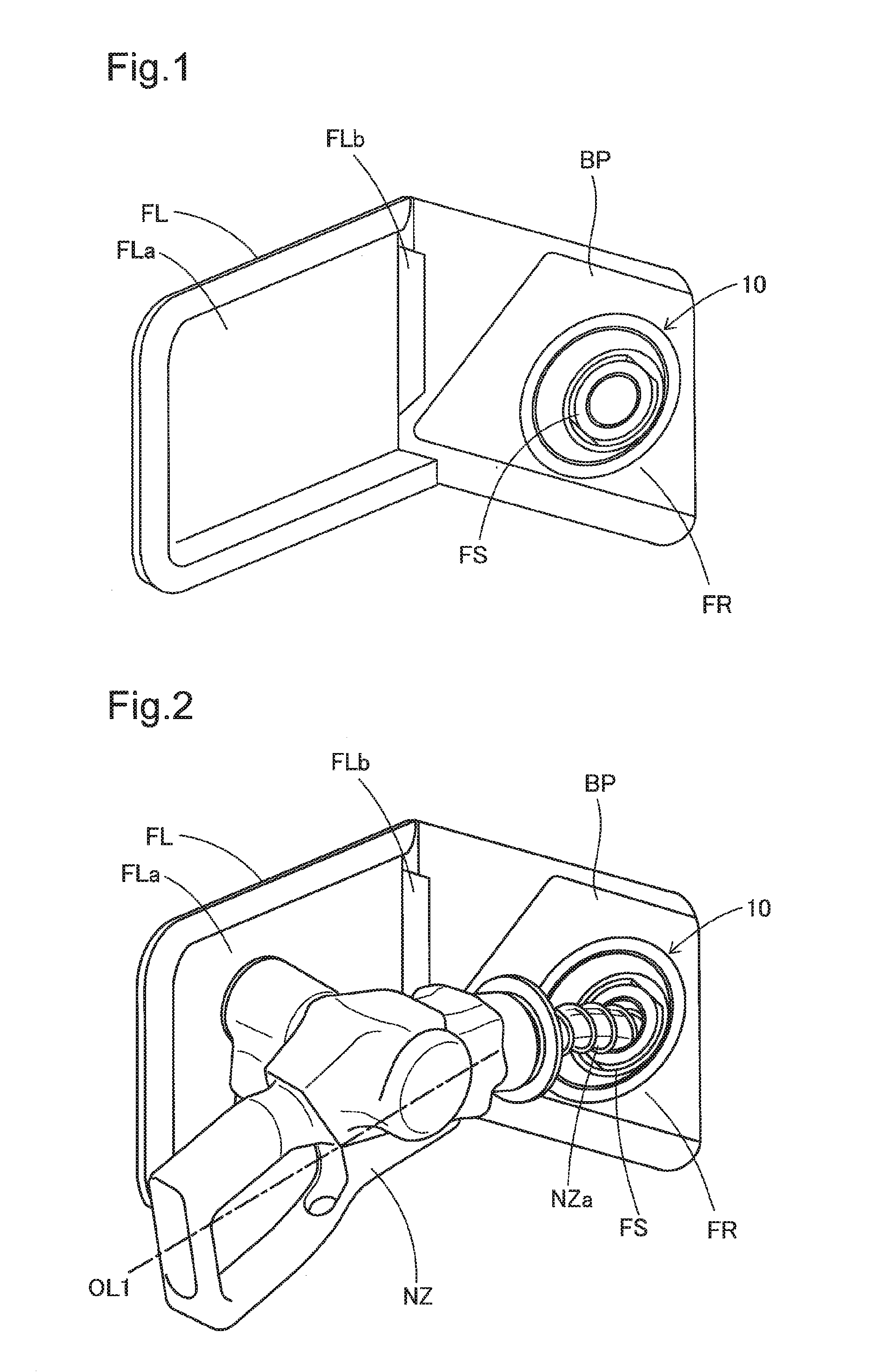
[0039]FIG. 1 is a perspective view illustrating a filler port of a motor vehicle that is equipped with a fuel supply apparatus FS according to an embodiment. FIG. 1 illustrates the fuel supply apparatus FS that is configured to form a fuel passage for introducing a supplied fuel to a fuel tank (not shown) provided inside of the motor vehicle, and members placed in a neighborhood of the fuel supply apparatus FS. A fuel lid FL is held in an openable and closable manner on the vehicle body of the motor vehicle. The fuel lid FL has a lid main body FLa formed in a shape along the outer panel of the vehicle body. The lid main body FLa is supported in an openable and closable manner on the outer panel of the vehicle body via a hinge FLb. The space accessible by opening the fuel lid FL serves as a fuel filler chamber FR. An open-close device 10 for fuel tank mounted on a base plate BP is placed in this fuel filler chamber FR. The op...


PUM


Abstract

An object is to provide a fuel supply apparatus that is configured to cause fuel vapor generated by vaporization of a fuel circulated in a fuel tank to be smoothly joined with the supplied fuel. The fuel supply apparatus comprises a filler neck body that is configured to include a hollow fuel passage-forming portion arranged to define a fuel passage and a breather port; a nozzle guide that is placed inside of the fuel passage-forming portion and is configured to introduce a fueling nozzle; a guide portion that is configured to introduce an inflow gas flowing in from the breather port, to the fuel passage via an outer circumferential space; and a rib that is provided between the guide portion and a lower end in the first direction of the nozzle guide and is configured to divide the inflow gas introduced through the fuel passage.

Description

CROSS-REFERENCE TO RELATED APPLICATIONS[0001]The present application claims priorities from Japanese patent applications P2015-55763 and P2015-55764 filed on Mar. 19, 2015, the content of which is hereby incorporated by reference into this application.TECHNICAL FIELD[0002]The present invention relates to a fuel supply apparatus.DESCRIPTION OF RELATED ART[0003]A fuel supply apparatus having an opening provided in the middle of a fuel passage to open and close the fuel passage has been known as a fuel supply apparatus configured to introduce a supplied fuel to a fuel tank of a motor vehicle. JP 2009-83569A describes a filler neck including a tubular body that is configured to form a fuel passage and a breather port that is arranged to branch off from the tubular body and to connect with a circulation path configured to circulate the fuel vapor generated in the fuel tank to the fuel passage. JP 2010-195062A describes a fuel supply apparatus having a filler neck including a tubular body...

Claims


Application Information

Patent Timeline
Patent Type & Authority Applications(United States)
IPC IPC(8): B60K15/04F02M37/00
CPCB60K15/04B60K2015/03368F02M37/0082F02M37/0076B60K2015/03538B60K2015/0464B60K2015/047
Inventor SEKIHARA, ATSUSHIHIRAMATSU, YOSHINARISHIMOKAWA, SHINJISHIRASAKI, TORU
Owner TOYODA GOSEI CO LTD
Why Eureka
Try Eureka