Detection of multi-rotors using electromagnetic signatures

a multi-rotor, electromagnetic signature technology, applied in the direction of direction finders, instruments, measurement devices, etc., can solve the problems of difficult detection in these conditions and commonplace incidents

Active Publication Date: 2016-10-20
ROBOTIC RES OPCO LLC
View PDF5 Cites 2 Cited by
  • Summary
  • Abstract
  • Description
  • Claims
  • Application Information

AI Technical Summary

Benefits of technology

The invention uses electromagnetic signals to identify and track multi-rotors, which are devices that use multiple electric motors to move. This helps to distinguish multi-rotors from other devices with electric motors. The invention also includes a control device to generate three-phase AC and measures the back EMF pulses to ensure proper motor timing. Overall, the invention improves the detection and rejection of false alarms for multi-rotor devices.

Problems solved by technology

Both accidental and purposeful attempts at reaching military and civilian government installations with UAVs have already transpired, including an accidental landing at the White House in April 2015.
As the cost lowers and the variety of multi-rotors proliferates, it is likely that such incidents will become commonplace.
Detection in these conditions is difficult, and often too late.

Method used


Image

  • Detection of multi-rotors using electromagnetic signatures
  • Detection of multi-rotors using electromagnetic signatures
  • Detection of multi-rotors using electromagnetic signatures

Examples


Embodiment Construction

[0023]In the following detailed description of the invention of exemplary embodiments of the invention, reference is made to the accompanying drawings (where like numbers represent like elements), which form a part hereof, and in which is shown by way of illustration specific exemplary embodiments in which the invention may be practiced. These embodiments are described in sufficient detail to enable those skilled in the art to practice the invention, but other embodiments may be utilized and logical, mechanical, electrical, and other changes may be made without departing from the scope of the present invention. The following detailed description is, therefore, not to be taken in a limiting sense, and the scope of the present invention is defined only by the appended claims.

[0024]In the following description, numerous specific details are set forth to provide a thorough understanding of the invention. However, it is understood that the invention may be practiced without these specifi...


PUM

PropertyMeasurementUnit
frequencyaaaaaaaaaa
frequenciesaaaaaaaaaa
pulse width modulationaaaaaaaaaa

Abstract

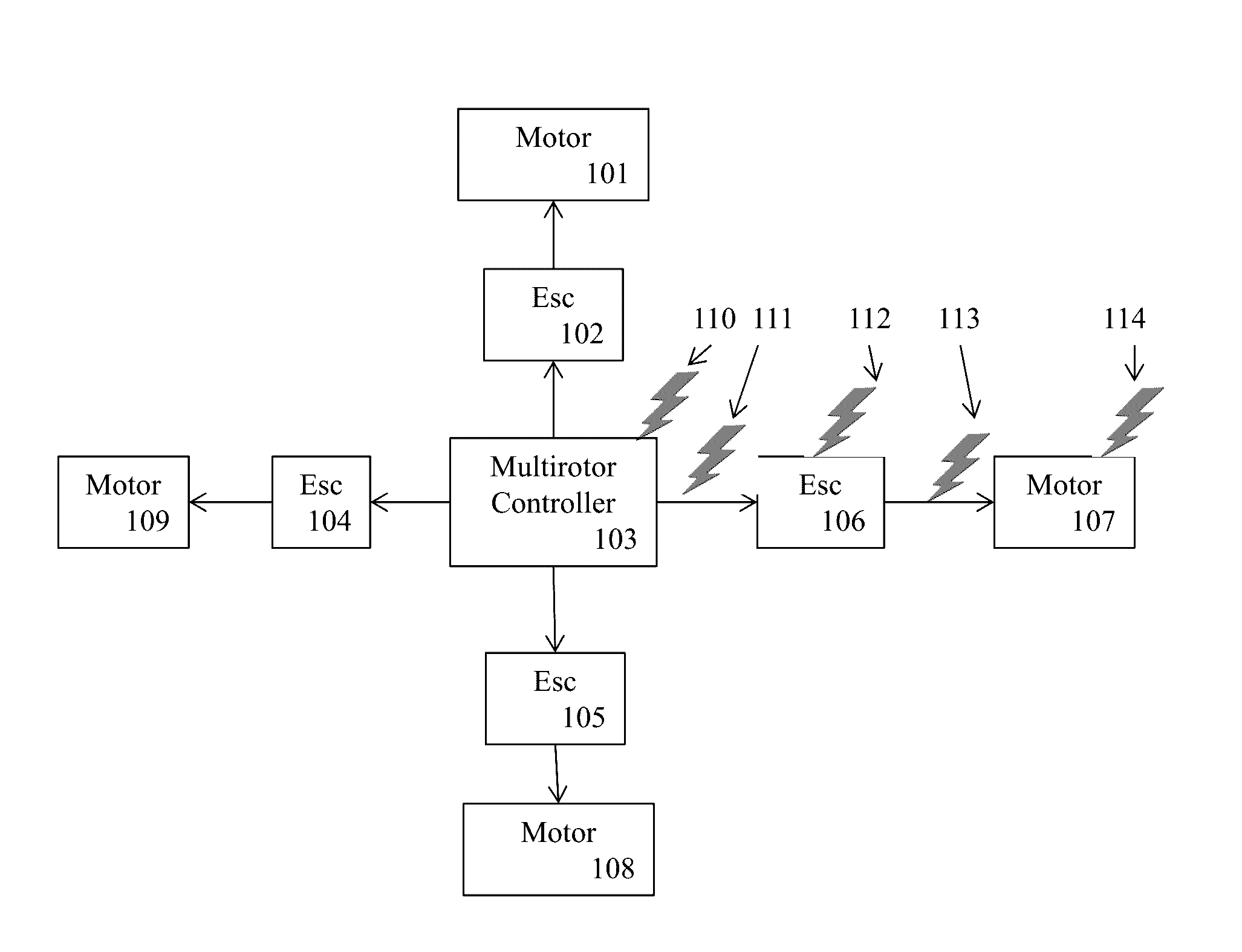
Multi-rotors use multiple electric motors to drive propellers that allow the multi-rotor to fly, turn, bank, etc. The multiple motors and the associated control device produce EM signals that can be used to detect multi-rotors and distinguish them from other devices with electric motors. To drive a brushless motor, the ESC takes DC from the battery and turns it into three phase AC (sinusoidal or trapezoidal wave), and then measures back EMF pulses (sensorless). This allows one to ensure that the three phase AC is being generated at the proper frequency to turn the motor (timing). For each propeller in the multi-rotor there are usually four different correlated signals at multiple frequencies that are used for detection and false alarm rejection.

Description

CROSS REFERENCE TO RELATED APPLICATIONS[0001]This application claims priority from U.S. patent application Ser. No. 62 / 129,471, entitled “DETECTION OF MULTI-ROTORS USING ELECTROMAGNETIC SIGNATURES”, filed on 20 Apr. 2015. The benefit under 35 USC §119(e) of the United States provisional application is hereby claimed, and the aforementioned application is hereby incorporated herein by reference.TECHNICAL FIELD OF THE INVENTION[0002]The present invention relates generally to the detection of air born vehicles. More specifically, the present invention relates to the detection of un manned air vehicles (UAVs) utilizing multi-rotors.BACKGROUND OF THE INVENTION[0003]Unmanned Air Vehicles (UAVs), and multi-rotors in particular, are starting to be used as tools to transport illegal contraband into prisons or across borders. In addition, they can be used as explosives, or as Chemical, Biological, Radiological, Nuclear and Explosive (CBRNE) delivery mechanisms. Both accidental and purposeful ...

Claims


Application Information

Patent Timeline
Patent Type & AuthorityApplications(United States)
IPC IPC(8): G01B7/14G01N27/02
CPCG01N27/02G01B7/14G01S5/0226G01S3/66G01S11/16G01S5/02524G01S5/018G01S2205/01
InventorLACAZE, ALBERTOMURPHY, KARL NICHOLAS
OwnerROBOTIC RES OPCO LLC