

Lens control device and lens control method
- Summary
- Abstract
- Description
- Claims
- Application Information
AI Technical Summary
Benefits of technology
Problems solved by technology
Method used
Image

Examples
Embodiment Construction
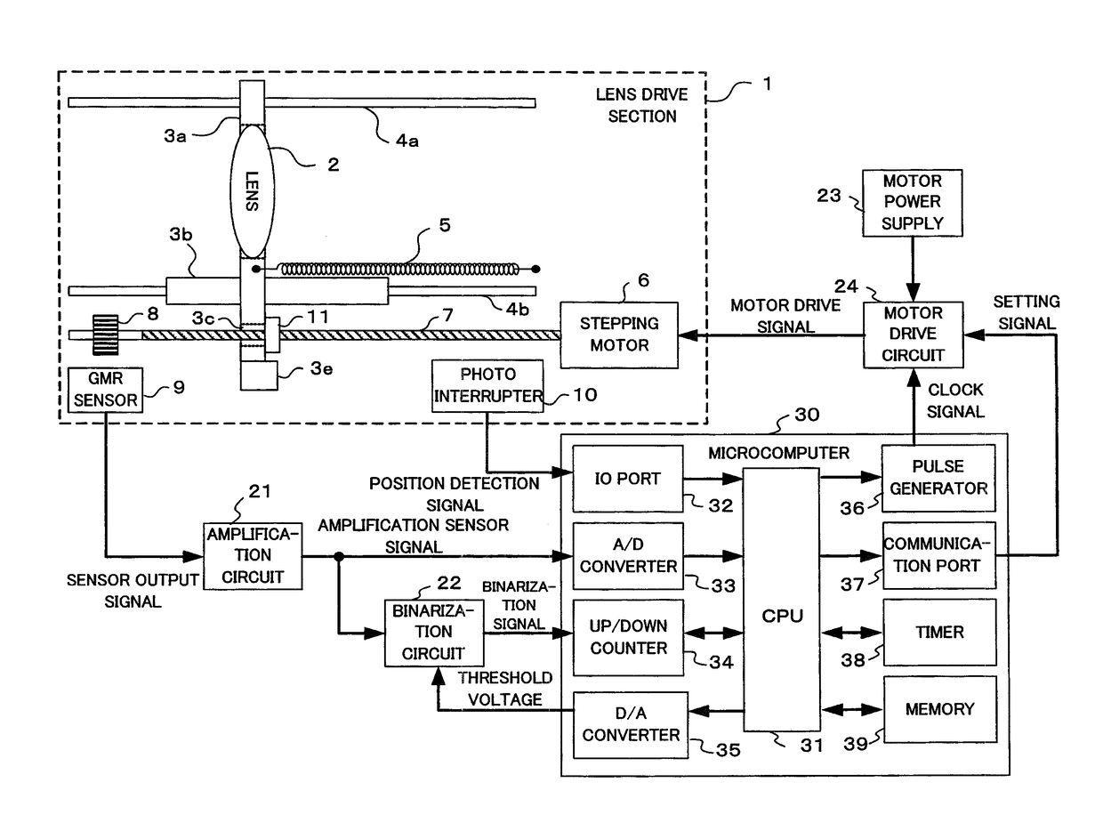
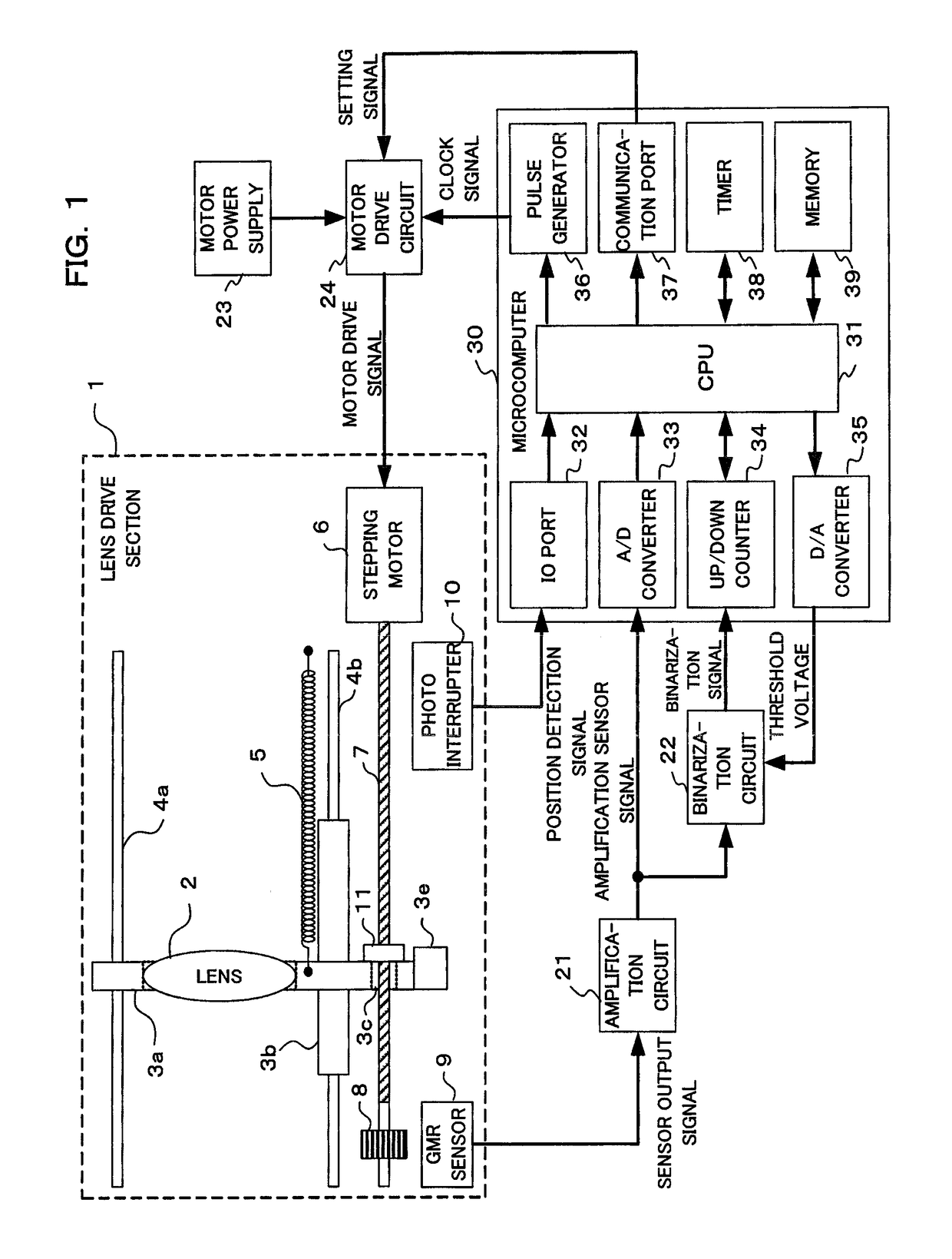
[0022]An example where a digital camera is adopted as one embodiment of the present invention will be described in the following. This camera converts a subject image, that has been formed by an optical lens within a lens barrel section, to image data using an imaging section, subjects the subject image to live view display on a display that is arranged on the rear surface of a camera body, based on this converted image data, and stores image data for a still picture or movie in a storage medium. In tandem with a half press operation of a release button or the like, focus detection is carried out using a contrast method or phase difference method etc., and an optical lens is moved to an in-focus position using drive of a stepping motor in accordance with the result of focus detection.
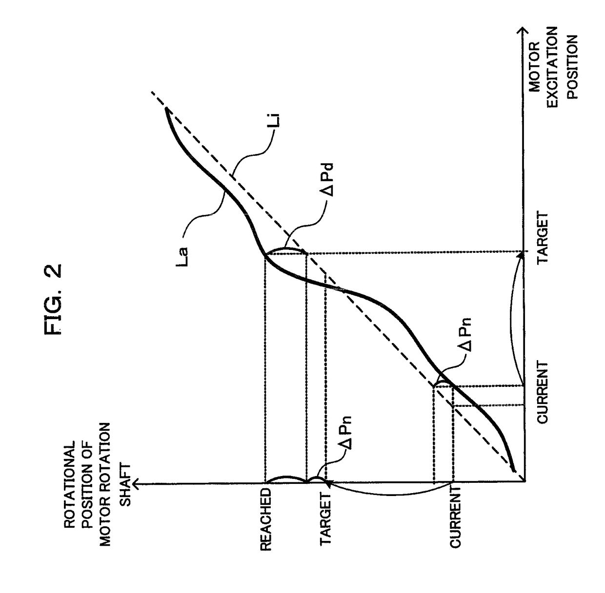
[0023]When moving to the in-focus position of the optical lens etc., virtual target rotational position is determined based on movement destination (target position) of the lens (refer, for example, to ...
PUM
 Abstract
Description
Claims
Application Information