Unlock instant, AI-driven research and patent intelligence for your innovation.

Device, System, and Method for Tracking an Object Using Radar Data and Imager Data

a technology of imager data and object tracking, applied in the direction of direction finders using radio waves, measurement devices, instruments, etc., can solve the problems of system general unsuitability for tracking fast moving objects, and inability to provide the desired level of accuracy

Active Publication Date: 2018-06-07
TRACKMAN
View PDF6 Cites 17 Cited by
  • Summary
  • Abstract
  • Description
  • Claims
  • Application Information

AI Technical Summary

Benefits of technology

The present invention is a system for tracking the movement of an object using a radar device and an imager. The radar device generates data indicating the distance of the object and the rate at which it is moving, while the imager measures the angular position of the object in at least two dimensions. By combining the radar data and imager data, the system can identify the track of the object in three dimensions. The system can measure the vertical and horizontal angles in an imager coordinate system and use a reference point system to calculate the position of the object in the field based coordinate system. The system can also use a prior knowledge of the object's location or speed to define a region of interest within which the object is expected to appear. The technical effect of this invention is to provide a more accurate and efficient system for tracking the movement of objects in three dimensions.

Problems solved by technology

However, these systems, which generally employ two-dimensional imagers, have been unable to provide the desired level of accuracy under certain conditions.
In addition, radar tracking systems used to track objects have also suffered from certain deficiencies.
However, such systems are generally unsuitable for tracking fast moving objects, such as sports balls, at short distances near the ground and other objects.
Thus, the receivers of such systems must be shut down when the pulse radar is transmitting or these highly sensitive receivers will be saturated or damaged by the high-power signal.
Furthermore, these systems are generally unable to discriminate between different objects at similar positions (e.g., a moving object passing close by a stationary object or an object moving on a different path).
These systems are, therefore, not well suited to situations involved in, for example, tracking an object such as a sports ball passing through an area near the ground and including other objects such as moving or stationary players, trees, etc.

Method used


Image

  • Device, System, and Method for Tracking an Object Using Radar Data and Imager Data
  • Device, System, and Method for Tracking an Object Using Radar Data and Imager Data
  • Device, System, and Method for Tracking an Object Using Radar Data and Imager Data

Examples


Embodiment Construction

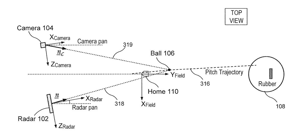
[0034]The exemplary embodiments may be further understood with reference to the following description and the related appended drawings, wherein like elements are provided with the same reference numerals. The exemplary embodiments relate to a device, a system, and a method for tracking objects by combining data from one or more imagers and one or more radar devices. Although exemplary embodiments detailed herein describe the tracking of baseballs and golf balls, those skilled in the art will understand that any sports balls or even non-sports related objects may be tracked with the system in the same manner. In the same manner, the system may track a baseball bat, a golf club or any other item that is detectable in the image and that generates a signal in the radar data.

[0035]FIGS. 1-4 show a first system 100 for tracking an object 106 according to the exemplary embodiments. The first system 100 includes two tracking devices—a radar tracking device 102 and an image tracking device ...


PUM


Abstract

A system for tracking the movement of an object includes a radar device having a first field of view. The radar device generates radar data indicating one of a range corresponding to a distance of a moving object within the first field of view from the radar device and a range rate corresponding to a rate at which the distance is changing relative to the radar device. The system also includes an imager having a second field of view at least partially overlapping the first field of view in an overlap field of view. The imager generates imager data measuring, when the object is in the second field of view, an angular position of the object relative to the imager in at least one dimension. In addition, the system includes a processor combining the radar data and imager data, when the object is in the overlap field of view, to identify a track of the object in at least two dimensions.

Description

BACKGROUND[0001]Tracking systems have used imagers capturing, for example, sequences of images of a target area including a moving object, to determining the position, speed and or trajectory of objects. However, these systems, which generally employ two-dimensional imagers, have been unable to provide the desired level of accuracy under certain conditions. In addition, radar tracking systems used to track objects have also suffered from certain deficiencies.[0002]Prior systems have attempted to cure these defects by combining pulse radar with imagers to track items such as planes and missiles. However, such systems are generally unsuitable for tracking fast moving objects, such as sports balls, at short distances near the ground and other objects. For example, a pulse radar system determines the range to an object by transmitting signals at high power and determining a time required for the return of a portion of these signals reflected by the object. As only a very small fraction ...

Claims


Application Information

Patent Timeline
IPC IPC(8): G01S13/89G01S7/02G01S3/802G01S13/93G01S17/89
CPCG01S13/89G01S7/02G01S17/89G01S13/93G01S3/802G01S13/32G01S13/536G01S13/58G01S13/70G01S13/867G01S13/88A63B69/36G01S3/02
Inventor TUXEN, FREDRIKSONDERGAARD, THOMAS
Owner TRACKMAN