Processing device, sheet manufacturing apparatus, processing method, and sheet manufacturing method

a processing device and sheet manufacturing technology, applied in papermaking, instruments, printing, etc., can solve the problems of insufficient removal of ink, long time required to remove ink, and the inability of the blasting material to reach ink, so as to achieve the effect of quick removal of color material

Active Publication Date: 2018-10-25
SEIKO EPSON CORP
View PDF0 Cites 3 Cited by
  • Summary
  • Abstract
  • Description
  • Claims
  • Application Information

AI Technical Summary

Benefits of technology

[0005]An objective of the several embodiments of the present invention is to provide a processing device, a sheet manufacturing apparatus, a processing method, and a sheet manufacturing method capable of quickly removing color material when color material is included in a material containing fiber.

Problems solved by technology

The blasting material therefore does not reach ink that has penetrated deeply into the thickness of the recording medium, and as a result cannot remove ink sufficiently.
Furthermore, to completely remove such ink, the recording medium must be sprayed with the blasting material for a sufficient time, and a long time may be required to remove the ink.

Method used


Image

  • Processing device, sheet manufacturing apparatus, processing method, and sheet manufacturing method
  • Processing device, sheet manufacturing apparatus, processing method, and sheet manufacturing method
  • Processing device, sheet manufacturing apparatus, processing method, and sheet manufacturing method

Examples


embodiment 1

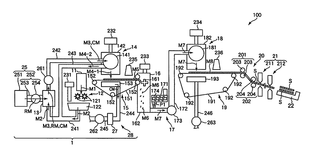
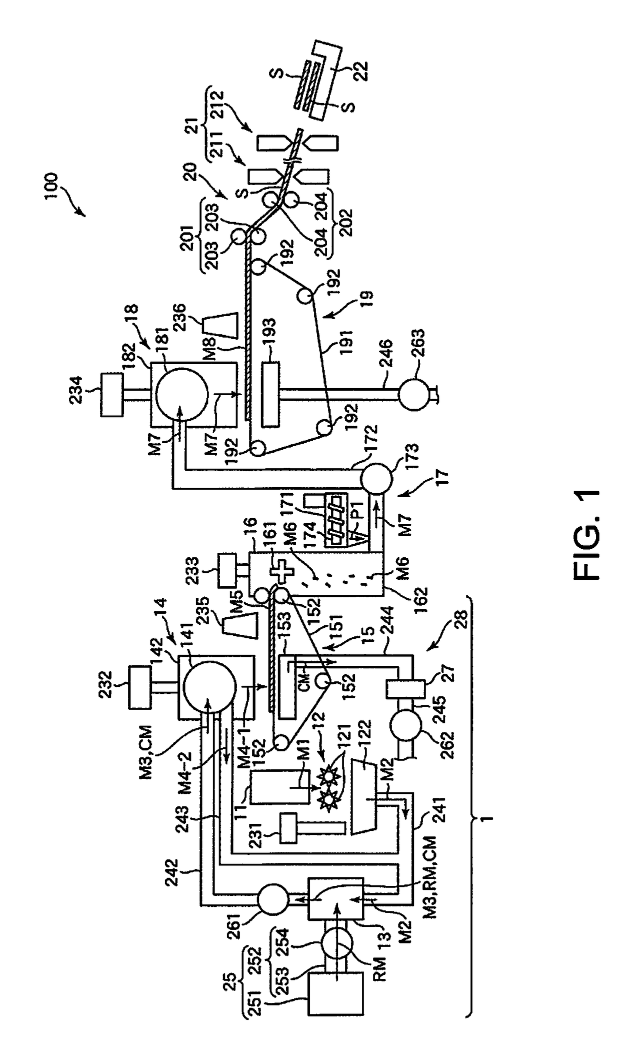
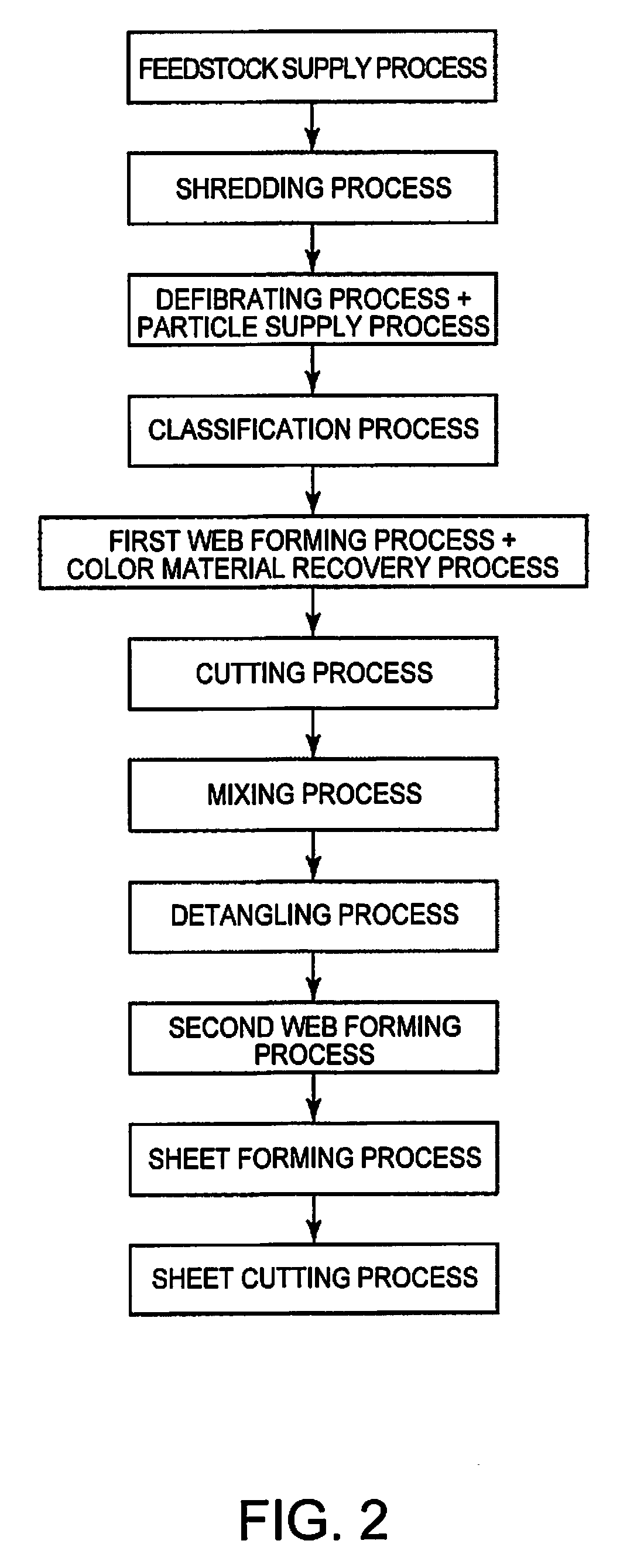
[0051]FIG. 1 is a side view schematically illustrating a first embodiment of a sheet manufacturing apparatus of the invention (including the processing device of the invention). FIG. 2 is a flow chart of steps executed by the sheet manufacturing apparatus shown in FIG. 1. FIG. 3 illustrates supplying particles in the sheet manufacturing apparatus shown in FIG. 1. FIG. 4 is a side view illustrating when color material is removed in the sheet manufacturing apparatus shown in FIG. 1.

[0052]Note that for convenience below, in FIG. 1 and FIG. 4 (and in FIG. 5 and FIG. 7), the side at the top is referred to as up or above; the bottom is referred to as down or below; the left side is referred to as the left or the upstream side; and the right side is referred to as the right or the downstream side.

[0053]The sheet manufacturing apparatus 100 shown in FIG. 1 has a feedstock supply device 11, a shredder 12, a defibrator 13, a particle supply device 25, a classifier 14, a first web forming devi...

embodiment 2

[0146]FIG. 5 is a side view schematically illustrating the upstream side of a second embodiment of a sheet manufacturing apparatus according to the invention (including a processing device of the invention). FIG. 6 is a flow chart of steps executed by the sheet manufacturing apparatus shown in FIG. 5.

[0147]A processing device, a sheet manufacturing apparatus, a processing method, and a sheet manufacturing method according to this second embodiment of the invention are described below with reference to the accompanying figures, focusing on the differences with the foregoing embodiment and omitting or simplifying further description of like parts.

[0148]This embodiment of the invention is the same as the first embodiment described above except that the particle supply device is disposed in a different location, and as a result, the timing of the particle supply process also differs.

[0149]As shown in FIG. 5, the sheet manufacturing apparatus 100 (processing device 1) has a conduit (flow...

embodiment 3

[0153]FIG. 7 is a side view schematically illustrating the upstream side of a third embodiment of a sheet manufacturing apparatus according to the invention (including a processing device of the invention). FIG. 8 is a flow chart of steps executed by the sheet manufacturing apparatus shown in FIG. 8.

[0154]A processing device, a sheet manufacturing apparatus, a processing method, and a sheet manufacturing method according to this third embodiment of the invention are described below with reference to the accompanying figures, focusing on the differences with the foregoing embodiments and omitting or simplifying further description of like parts.

[0155]This embodiment of the invention is the same as the first embodiment described above except that the color material recovery device is disposed in a different location, and the configuration of the color material recovery device differs.

[0156]As shown in FIG. 7, the color material recovery device 28 in this embodiment is disposed to the ...


PUM

PropertyMeasurementUnit
average particle diameteraaaaaaaaaa
particle diameteraaaaaaaaaa
sizeaaaaaaaaaa

Abstract

A processing device, a sheet manufacturing apparatus, a processing method, and a sheet manufacturing method enable quickly removing color material when color material is contained in a material containing fiber. A processing device has a defibrator configured to defibrate, in air, fibrous material containing fiber; and a particle supply device configured to supply particles of dry ice to the material containing fiber during defibration or after defibration. The material containing fiber contains color material; and the particles work to separate the color material for the fibers by colliding with the color material contained in the material containing fiber.

Description

BACKGROUND1. Technical Field[0001]The present invention relates to a processing device, a sheet manufacturing apparatus, a processing method, and a sheet manufacturing method.2. Related Art[0002]As concerns about the environment and environmental awareness have increased, there is growing interest in not only reducing the amount of paper (recording media) that is used in the workplace, but also in recycling and remanufacturing paper in the workplace.[0003]JP-A-2000-284657, for example, describes, as a method of recycling recording media, a method of spraying the recorded layer (printed surface) of a used recording medium, which is a paper sheet and has been printed on, with a blasting material to remove the recorded layer. After the recorded layer has been removed, the recording medium can then be used again.[0004]However, the recycling method described in JP-A-2000-284675 sprays sheets of the recording medium with the blasting material. The blasting material therefore does not reac...

Claims


Application Information

Patent Timeline
Patent Type & Authority Applications(United States)
IPC IPC(8): D21B1/08
CPCD21B1/08B41J29/26G03G21/00D21B1/325D21F9/00Y02W30/64
Inventor KUNUGI, MASANAOYOSHIOKA, SATOMI
Owner SEIKO EPSON CORP
Why Eureka
Try Eureka