Window jamb extender for new or replacement window

a technology for extending windows and windows, applied in the direction of windows/door frames, doors/windows, window/door frames, etc., can solve the problems of high interior finish work, replacement windows cannot fit in the existing jamb mounting depth of the structure, and requires additional labor and materials to complete the installation

Inactive Publication Date: 2019-04-18
WINJET LLC
View PDF7 Cites 5 Cited by
  • Summary
  • Abstract
  • Description
  • Claims
  • Application Information

AI Technical Summary

Problems solved by technology

This often requires additional labor and materials to complete the installation compared to the insert replacement method.
Attempting to install these replacement windows in the existing master frame or jamb of the structure causes various problems.
In contrast, a replacement window frame is normally 3′A-inches thick between the interior and exterior faces of the window frame, so such a replacement window will not fit in the existing jamb mounting depth of the structure.
Such interior finish work is costly, disruptive to the homeowner or other occupant, and otherwise undesirable.
As such, this second method is also undesired.
Finding or manufacturing such windows that fit an existing jamb mounting depth can increase cost and are commonly less energy efficient.
This cladding removal, frequently vinyl siding, is difficult because if a piece of siding is damaged and needs to be replaced it is difficult to match siding that has faded or may no longer be available from the original manufacturer.
Overall, the exterior cladding work required to remove and reinstall the cladding around every window in the home, around existing landscaping, variable exterior grading, working with scaffolding when required, is very time and cost intensive.
Hence, there is a long felt but unresolved need for an apparatus and method that prevent the need for increasing the jamb mounting area to the interior of the home.

Method used


Image

  • Window jamb extender for new or replacement window
  • Window jamb extender for new or replacement window
  • Window jamb extender for new or replacement window

Examples


first embodiment

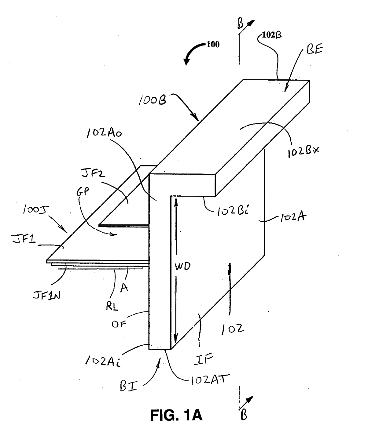
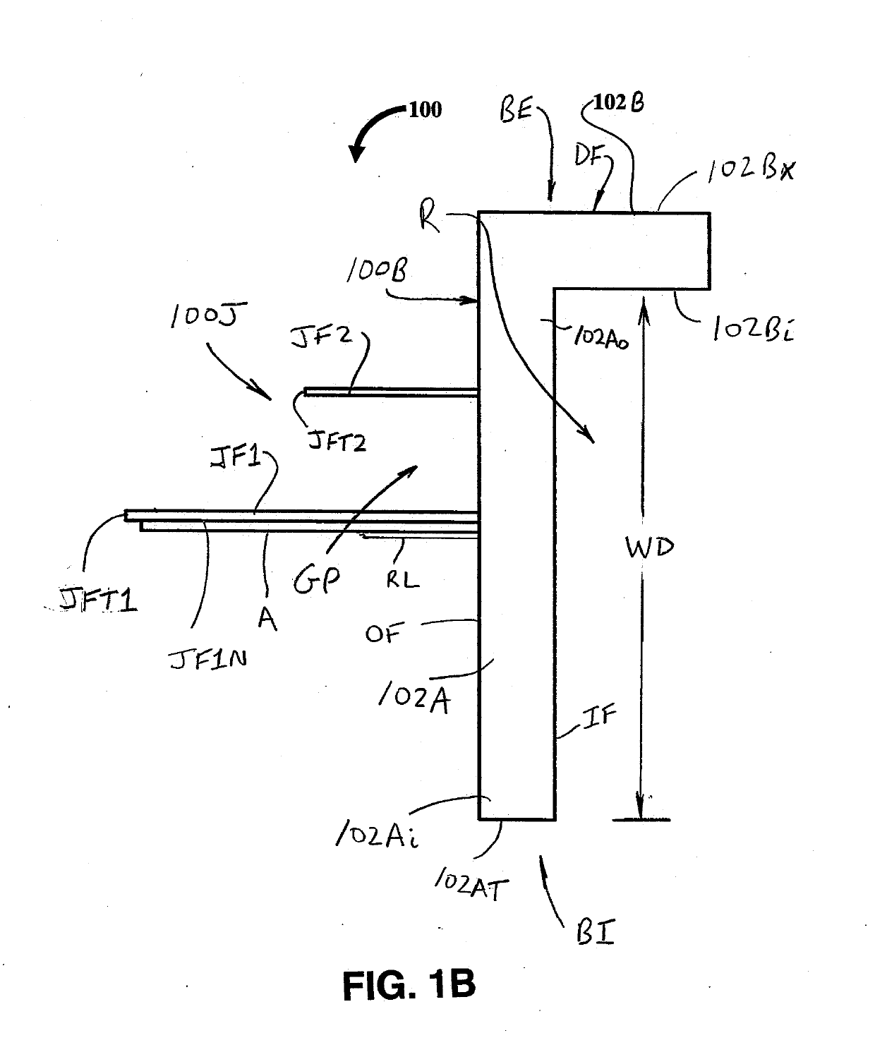
[0022]FIGS. 1A and 1B illustrate a window jamb extender 100 formed in accordance with the present development. In a typical arrangement, as described in more detail below, four separate sections of the window jamb extender 100 are installed in a window opening of an associated wall of a house or other structure and arranged in a rectangular shape to construct a master window frame within which a vinyl frame or other new or replacement window can be operatively installed in a manner that eliminates or minimizes finish work on the interior side of the window.

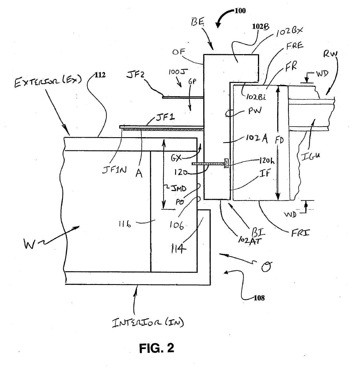
[0023]Referring also to FIG. 2, the window jamb extender 100 overcomes the deficiencies associated with known window installation methods and structures by providing a structure that accommodates a frame FR of a replacement window within an existing jamb mounting depth JMD of a window jamb 106 existing in an opening O of an associated wall structure W of a house or other structure as shown in FIG. 2.

[0024]The window jamb extender ...

second embodiment

[0037]FIG. 4A is an exploded end view of a window jamb extender 200 formed in accordance with the present development. FIG. 4B is similar to FIG. 4A but shows the window jamb extender 200 fully assembled and illustrates an associated fastener 120 used to operatively secure the window jamb extender 200 to the associated wall W of a house or other structure. FIG. 4C is similar to FIG. 4B but also shows the window jamb extender 200 operatively installed in a window opening O of an associated house / structure wall W, and shows an associated window RW operatively engaged with the window jamb extender. FIG. 4D is an isometric view of the frame portion of the window jamb extender of FIG. 4A cut at a 45 degree angle to form a corner miter edge to be joined with a like frame portion to form a corner miter joint. Except as otherwise shown and / or described herein, the window jamb extender 200 is identical to the window jamb extender 100. As such, like reference numbers and letters are used to d...

embodiment 100

[0042]The first leg 202A is defined to include an outer face channel or outer face recess OFR that provides a location where the connecting wall JW of the J-channel 200J is adhered or otherwise connected to the outer face OF of the L-shaped frame 202. The outer face recess OFR is recessed, depressed, or offset inwardly relative to an adjacent portion of the outer surface OF includes or defines a width CW that can exactly match the corresponding width of the J-channel connecting wall JW, but preferably the width CW of the outer face recess OFR is larger than the corresponding width of the J-channel connecting wall JW to allow for customization with respect to the exact location of the J-channel 200J on the outer surface OF within an acceptable range as defined by the width CW of the outer face recess ODR. In the illustrated embodiment, the J-channel connecting wall JW is secured to the outer face OF in the outer face recess OFR using double-sided tape, but any other adhesive or other...


PUM

PropertyMeasurementUnit
depthaaaaaaaaaa
angleaaaaaaaaaa
thicknessaaaaaaaaaa

Abstract

A window jamb extender includes a frame including: (i) a first leg including opposite inner and outer ends; and, (ii) a second leg connected to the outer end of the first leg and arranged transversely relative to the first leg. The first leg includes an outer face adapted to be abutted with an associated wall stud that partially defines a periphery of an opening in an associated wall structure. The first leg includes an inner face that is opposite the outer face and that is adapted to lie adjacent an outer peripheral wall of an associated window frame. The second leg includes an inner face adapted to lie adjacent an exterior face of the associated window frame. The window jamb extender further includes a primary flange that projects outwardly from the outer face of said first leg.

Description

CROSS-REFERENCE TO RELATED APPLICATIONS[0001]This application is a continuation-in-part of U.S. application Ser. No. 15 / 621,700 filed Jun. 13, 2017, which is a continuation-in-part of U.S. application Ser. No. 15 / 356,409 filed Nov. 18, 2016, which claims priority from and benefit of the filing date of U.S. provisional application Ser. No. 62 / 392,878 filed Jun. 13, 2016, and the entire disclosure of each of said prior applications is hereby expressly incorporated by reference into the present specification. Said prior application Ser. No. 15 / 621,700 also claims priority from and benefit of the filing date of U.S. provisional application Ser. No. 62 / 392,878 filed Jun. 13, 2016.FIELD[0002]The present invention relates to a device to modify jamb dimensions to ease carpentry work on windows. More particularly, the present invention relates to a window jamb extender configured to allow installation of new windows, either as replacement windows in an existing home or other structure, or as...

Claims


Application Information

Patent Timeline
Patent Type & Authority Applications(United States)
IPC IPC(8): E06B1/02E06B1/26E06B1/34E06B1/36E06B1/60
CPCE06B1/02E06B1/26E06B1/342E06B1/36E06B1/6023E06B1/6015E06B1/62E06B1/68
Inventor ROCCA, JR., SAMUEL MARKSCHMIDT, TODD R.SCHMIDT, RUSSELL E.FELKER, TIMOTHY E.
Owner WINJET LLC
Why Eureka
Try Eureka