Proportional hydraulic valve

a hydraulic valve and proportional technology, applied in the direction of valves, multiple way valves, mechanical devices, etc., can solve the problems of increased back pressure at the valve piston and volume flow also decrease, so as to reduce or suppress undesirable vibration, improve response behaviour, and reduce the effect of vibration

a hydraulic valve and proportional technology, applied in the direction of valves, multiple way valves, mechanical devices, etc., can solve the problems of increased back pressure at the valve piston and volume flow also decrease, so as to reduce or suppress undesirable vibration, improve response behaviour, and reduce the effect of vibration

US20200332911A1Active Publication Date: 2020-10-22HAWE HYDRAULIK SE

Image

  • Proportional hydraulic valve
  • Proportional hydraulic valve
  • Proportional hydraulic valve

Examples


Embodiment Construction

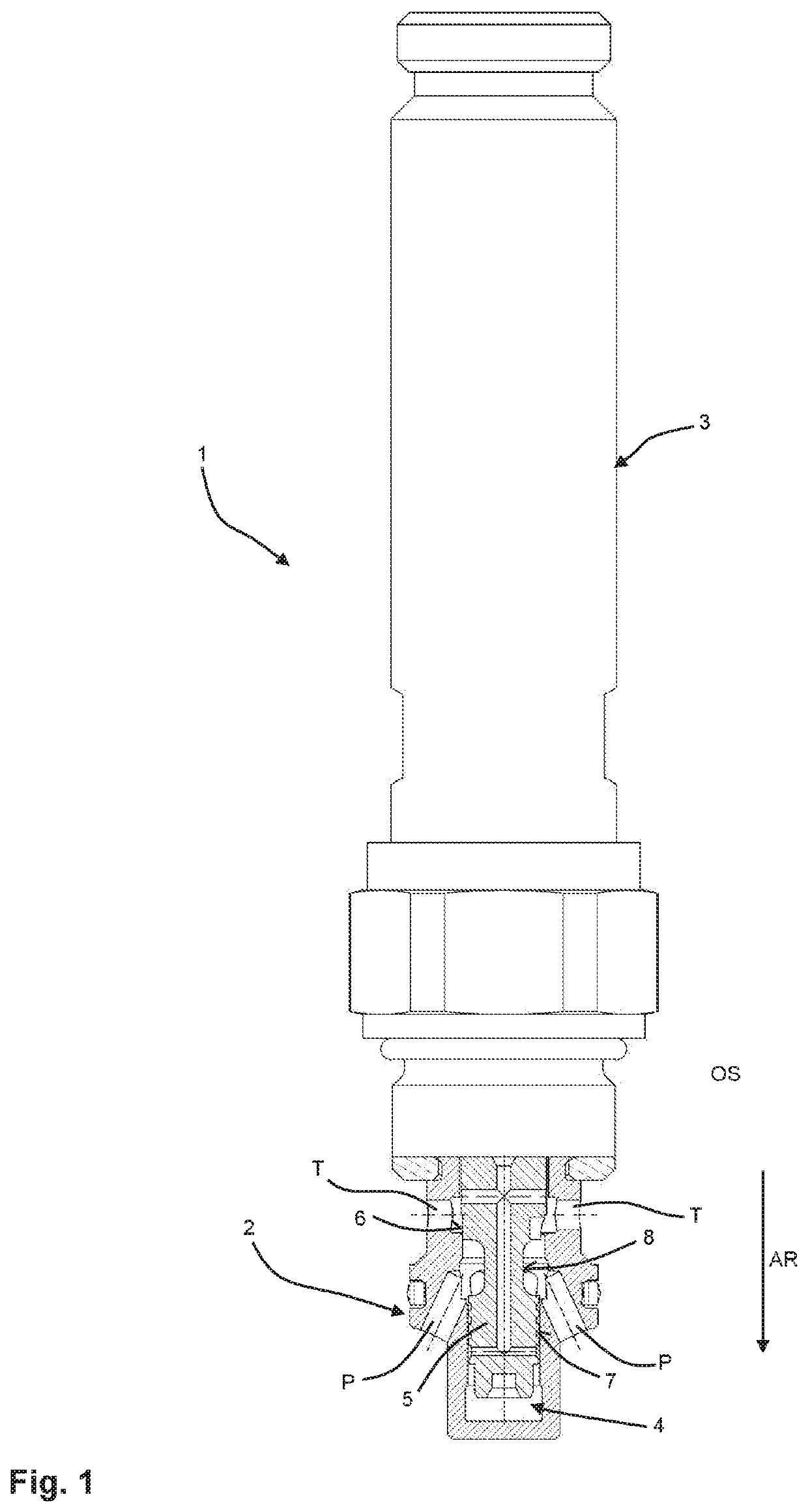
[0029]In FIG. 1 a proportional hydraulic valve 1 according to the invention is shown as a partial sectional view. In this embodiment, the proportional hydraulic valve 1 is a proportional pressure limiting valve. However, the hydraulic valve 1 can of course also be configured in such a way that it fulfils another hydraulic function, for example as a pilot-operated check valve. The proportional pressure limiting valve 1 has a valve housing 2 (shown cut in FIG. 1) and an actuating device 3. In addition, the valve housing 2 has several pressure connections P arranged radially circumferentially at regular intervals and several connecting ports T axially spaced from the pressure connections and also disposed radially circumferentially at regular intervals. In this embodiment, the connection ports T represent tank connections. In this embodiment, the pressure connections P are inclined and the tank connections T are arranged perpendicular to the valve piston 5. The inclination of the press...


PUM


Abstract

A proportional hydraulic valve has a valve housing, an actuating device and a valve piston axially movable in a piston chamber of the valve housing. The valve housing has at least one pressure connection and at least one connection port. The valve piston blocks a flow path between the pressure connection and the connection port or releases it proportionally by moving the valve piston proportionally to an actuating force generated by the actuating device between a closed position and an open position. The valve piston has a first and a second spool area with a circumferential recess in the axial direction after the first and before the second spool area. The recess together with the piston chamber forms a pressure chamber and the pressure connection opens into the pressure chamber. A first diameter of the first spool area is larger than a second diameter of the second spool area.

Description

CROSS-REFERENCE TO RELATED APPLICATION[0001]This application claims priority from German Application No. 10 2019 205 640.7 filed Apr. 17, 2019, the entire content of which is incorporated herein by reference.FIELD OF THE INVENTION[0002]The present invention relates to a proportional hydraulic valve with a valve housing, an actuating device and a valve piston axially movable in a piston chamber of the valve housing.BACKGROUND OF THE INVENTION[0003]In such valves, the valve housing has at least one pressure connection and at least one connection port. The valve piston blocks a flow path between the pressure connection and the connection port or proportionally releases this flow path by the valve piston moving between a closed position and an open position in the piston chamber in proportion to an actuating force generated by the actuating device. The connection port is often a tank port or return connection. Such a proportional hydraulic valve is known from DE 10 2005 022 693 A1, for ...

Claims


Application Information

Patent Timeline
22 Oct 2020
Publication
US20200332911A1
IPC
F16K31/06
CPC
F16K31/0693; F16K31/0696; F16K31/0613; F16K31/163; F16K31/363; F15B13/022; F15B13/027; F16K11/0716
Inventors
WECHSEL, THOMAS; FABER, BERND