Connector

Active Publication Date: 2020-10-29
MOLEX INC
View PDF0 Cites 4 Cited by
  • Summary
  • Abstract
  • Description
  • Claims
  • Application Information

AI Technical Summary

Benefits of technology

[0019]In the present disclosure, a connecter can be provided so that the interval between protrusions where the plu

Problems solved by technology

As a result, the contact pressure of the first contact part 855a and the second contact part 856a onto the cou

Method used


Image

  • Connector
  • Connector
  • Connector

Examples


Embodiment Construction

[0027]An embodiment will be described in detail below with reference to the drawings.

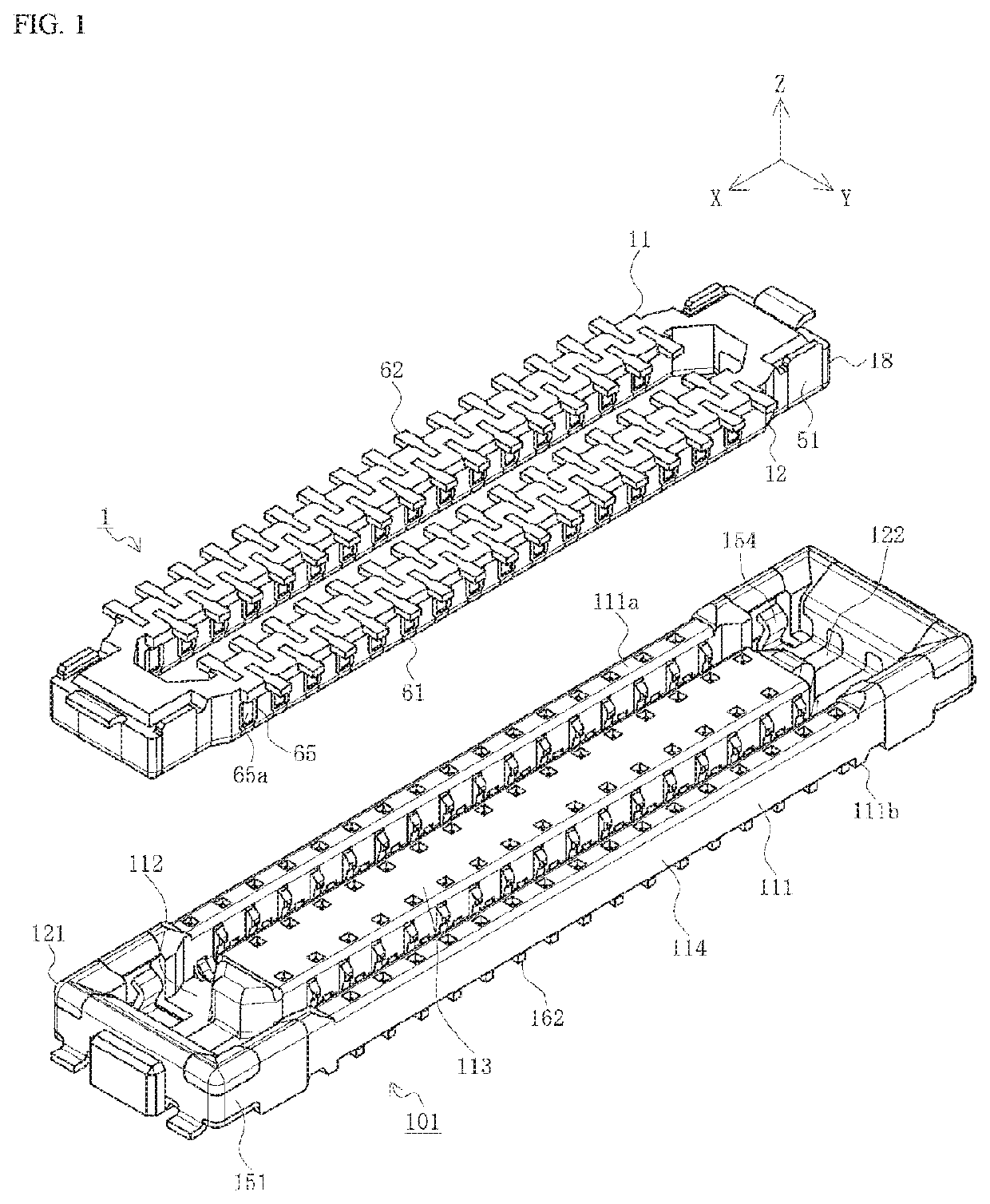
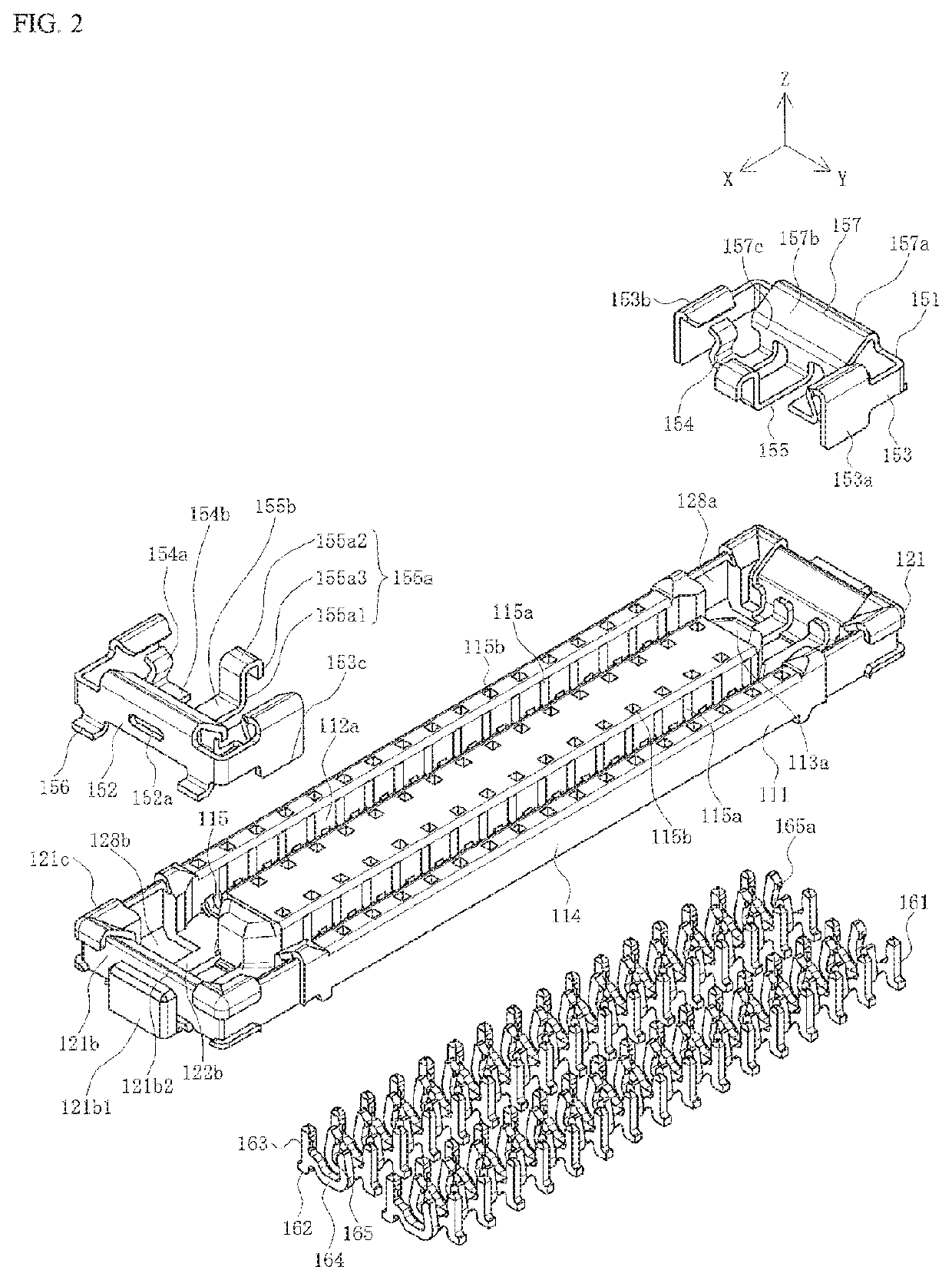
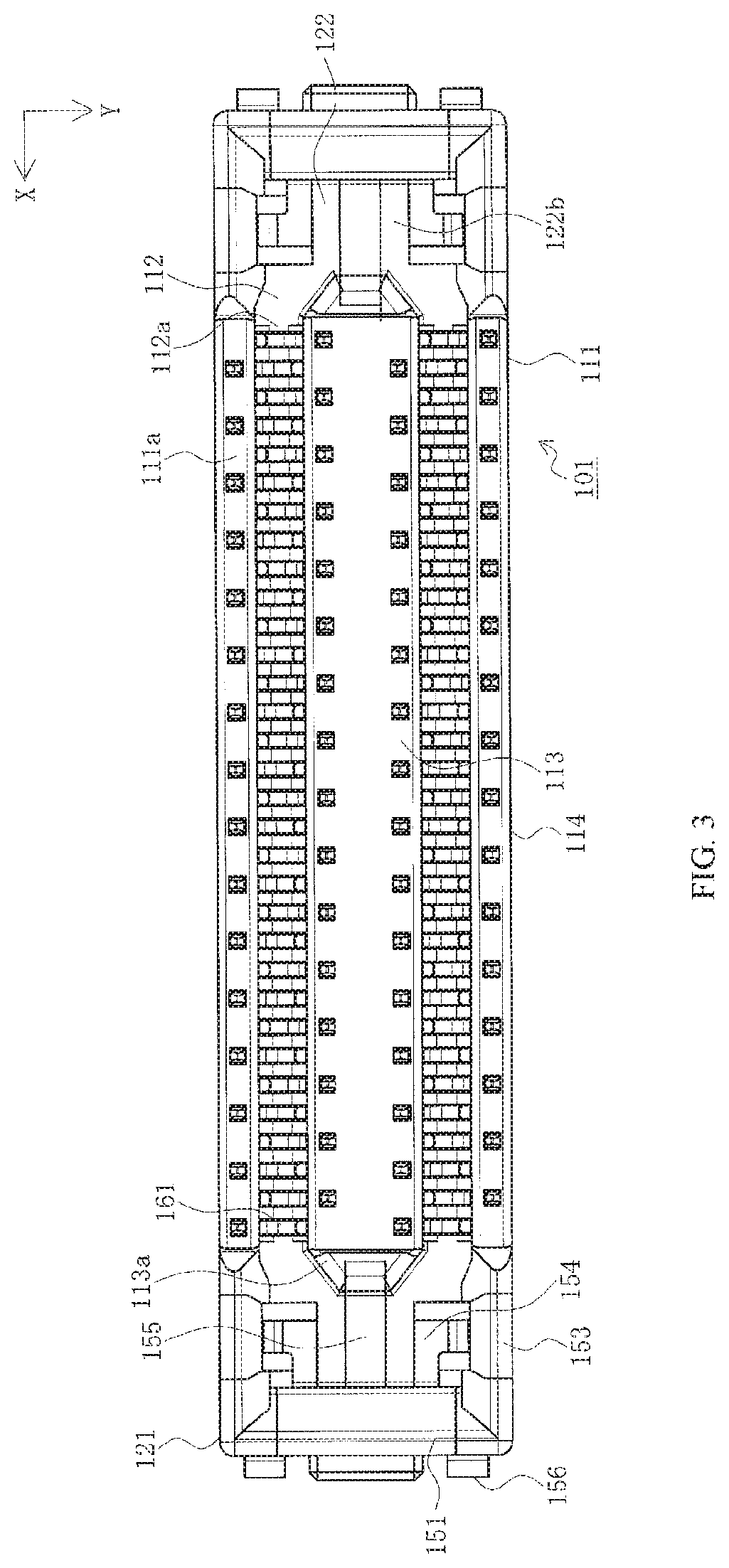
[0028]FIG. 1 is a perspective view illustrating the state immediately before mating of a first connector with a second connector according to the present embodiment when viewed from the first connector side, FIG. 2 is an exploded view illustrating the second connector according to the present embodiment, FIG. 3 is a top view illustrating the second connector according to the present embodiment, FIG. 4 is a bottom view of the second connector according to the present embodiment, and FIGS. 5A and 5B are two-sided views illustrating a second reinforcing bracket of the second connector. Note that FIG. 5A is a top view, and FIG. 5B is a front view.

[0029]In the figures, 101 is a second connector of a pair of board to board connectors which is a connector according to the present embodiment. The second connector 101 is a surface mount type connector to be mounted on the surface of a second substrate that i...


PUM


Abstract

A connector body includes a mating guide part having a mating recess, a reinforcing bracket includes a body part attached to the outer side of an end wall part of the mating guide part, an end wall cover part connected to an upper end of the body part and covers an upper side and an inner side of the end wall part, and a contact arm connected to a lower end of the end wall cover part, the contact arm includes a bottom surface part extending along a bottom surface of the mating recess and an upright part extending upward from a tip of the bottom surface part, and the upright part includes a contact projection near a tip thereof, the contact projection extending toward the center in the width direction of the connector body.

Description

RELATED APPLICATION[0001]This application claims priority to Japanese Application Serial No. 2019-134425, filed on Jul. 22, 2019 and U.S. Provisional application No. 62 / 838,345 filed on Apr. 25, 2019, which are incorporated by reference in their entirety.TECHNICAL FIELD[0002]The present disclosure relates to a connector.BACKGROUND ART[0003]Conventionally, connectors such as board to board connectors, etc., have been used to electrically connect pairs of parallel circuit boards together. These types of connectors are attached to mutually facing surfaces on pairs of circuit boards and provide conduction when mated together (for example see patent document 1).[0004]FIG. 7 is a partially exploded perspective view illustrating a known connector.[0005]In the drawing, 811 is a connector housing mounted on a circuit board (not illustrated), which has a pair of narrow long side wall parts 814 extending in the longitudinal direction and a projection 813 extending in the longitudinal direction...

Claims


Application Information

Patent Timeline
IPC IPC(8): H01R12/71H01R12/57H01R12/70H01R13/447H01R13/631H01R13/627H01R13/639
CPCH01R13/6395H01R13/6275H01R12/57H01R12/707H01R13/447H01R12/716H01R13/631H01R24/005H01R13/502H01R12/71H01R13/627H01R24/00H01R13/504H01R13/405H01R12/7088H01R12/73H01R13/20H01R13/629
Inventor GONDO, DAISHI
Owner MOLEX INC
Why Eureka
Try Eureka