Light guide pointer and light emitting pointer device

a technology of light guide pointer and light emitting pointer, which is applied in the direction of measurement devices, measurement apparatus components, instruments, etc., can solve the problems of uneven illumination in the extending direction, and achieve the goal of preventing the attenuation of light traveling, reducing the length of the inclined portions, and broadening the diffusion range of light passing through the light control space

Active Publication Date: 2021-02-04
YAZAKI CORP
View PDF0 Cites 0 Cited by
  • Summary
  • Abstract
  • Description
  • Claims
  • Application Information

AI Technical Summary

Benefits of technology

[0007]According to the light guide pointer of the present invention described above, since the vertex portion of the light control space is located on the sub-pointer portion side with respect to the center axis of the light entrance shaft, the light that has entered from the light entrance shaft is more reflected by the inclined portion on the main pointer portion side than the inclined portion on the sub-pointer portion side. Consequently, the light is guided more to the longer main pointer portion, thereby providing an appropriate balance between luminance at the main pointer portion and luminance at the sub-pointer portion. Further, since the light control space includes the circular arc portion, the range of diffusion of the light that has passed through the light control space can be broadened. In addition, the length of the inclined portions can be decreased, thereby preventing the attenuation of the light traveling along the inclined portions.
[0008]Since the light is not likely to be reflected at the vertex portion, the light that has entered the light control space from the vertex portion has higher intensity than the light that has entered the light control space from other portions. When the light enters the light control space from the vertex portion, the light refracts at a boundary surface between the light control space and the member constituting the light guide pointer and may travel toward the main pointer portion side. At this time, since the center of the circular arc portion is located on the main pointer portion side with respect to the center axis, the strong light can be diffused by the light control space. Herein, when the circular arc portion is constituted of a plurality of circular arcs, the center of the circular arc portion may be, for example, a center of the longest circular arc or a center of the circular arc located at a central portion in the intersecting direction.
[0009]Therefore, according to the light guide pointer of the present invention, it is possible to provide an appropriate balance between luminance on the main pointer portion side and luminance on the sub-pointer portion side and it is also possible to prevent local focusing of light and / or attenuation of light, thereby reducing the luminance unevenness at the light emitting face.

Problems solved by technology

However, merely forming the trapezoidal light control part as described in Patent Document 1 has a drawback that, although it can reflect light so as to direct the light in an extending direction of the pointer, it is likely to cause luminance unevenness in the extending direction.

Method used


Image

  • Light guide pointer and light emitting pointer device
  • Light guide pointer and light emitting pointer device
  • Light guide pointer and light emitting pointer device

Examples


Embodiment Construction

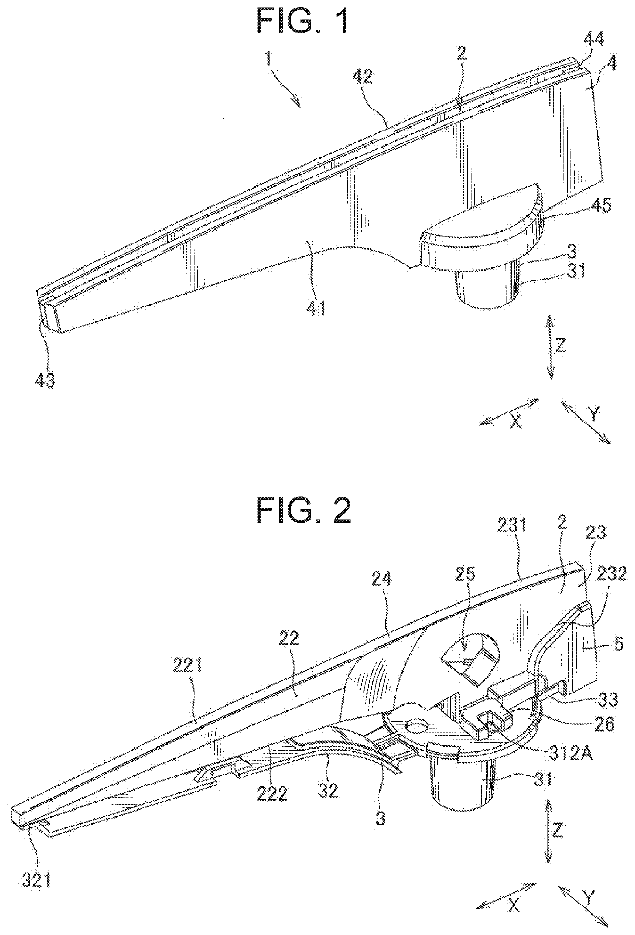
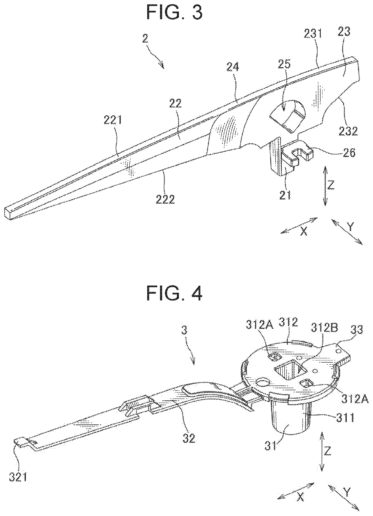
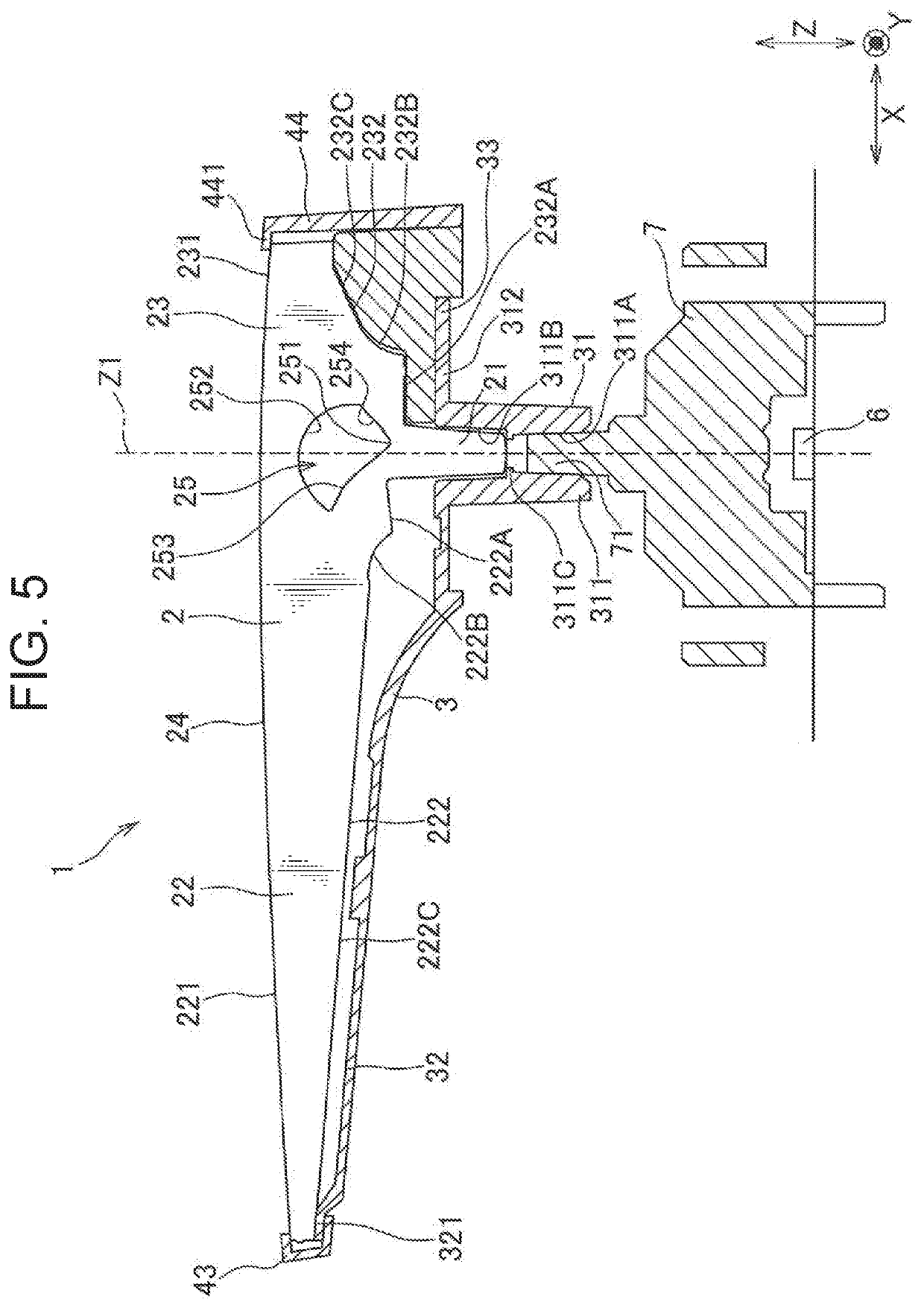
[0021]In the following, each embodiment of the present invention will be explained with reference to the drawings. As shown in FIG. 1 to FIG. 5, a light emitting pointer device 1 of this embodiment is provided with a pointer body (light guide pointer) 2, a base 3 as a holding member, a cap 4, a balance 5, a light source 6 and a light guide member 7, and is used in a vehicle display device (e.g., a speedometer) for pointing letters, numbers or the like. In this embodiment, a direction of a rotation shaft of the pointer body 2 is referred to as a Z direction, an extending direction of the pointer body 2 is referred to as an X direction, and a direction substantially orthogonal to both of the X direction and the Z direction is referred to as a Y direction. Further, in the Z direction, a side that is viewed by a user is referred to as an upper side, and a side opposite thereto is referred to as a lower side, and these can be merely expressed as upward and downward, respectively.

[0022]Th...


PUM


Abstract

In a light guide pointer, a vertex portion of a light control space is located on a sub-pointer portion side with respect to a center axis of a light entrance shaft, providing appropriate luminance balance between a main pointer portion and the sub-pointer portion. The light control space includes a circular arc portion, thereby broadening diffusion range of light that has passed through the light control space and preventing attenuation of light traveling along inclined portions. A center of the circular arc portion is located on the main pointer portion side with respect to the center axis, allowing strong light that has entered the light control space from the vertex portion to be diffused more. Local focusing and/or attenuation of light can be prevented, while providing appropriate luminance balance between the main pointer portion side and the sub-pointer portion side, thereby reducing luminance unevenness at the light emitting face.

Description

TECHNICAL FIELD[0001]The present invention relates to a light guide pointer and a light emitting pointer device.BACKGROUND[0002]Conventionally, there has been proposed a meter device that is provided with a light source, a pointer having a light guiding property and a dial plate, and that is configured such that light from the light source that has entered the pointer is totally reflected inside the pointer and is emitted from a surface (a light emitting face) of the pointer (for example, refer to Patent Document 1). In the meter device described in Patent Document 1, a light control part which is a trapezoidal through hole is formed on the pointer, and the light entering the pointer from a rotation shaft is reflected by side face portions of the light control part and is directed toward a tip end side of the pointer.PRIOR ART DOCUMENTPatent Document[0003]Patent Document 1: JP 2013-88351 ASUMMARY OF THE INVENTIONProblem to be Solved[0004]For the pointer having the light emitting fac...

Claims


Application Information

Patent Timeline
Patent Type & Authority Applications(United States)
IPC IPC(8): G01D11/28B60K37/02G01P1/10
CPCG01D11/28B60K37/02B60K2370/341B60K2370/336G01P1/10B60K35/00B60K2370/6992G01D13/265G01P1/08
Inventor MOCHIZUKI, YASUFUMIKUBOYAMA, TERUKAZUSHIBAHARA, AMI
Owner YAZAKI CORP
Why Eureka
Try Eureka