Touch pad and computer

a touch pad and computer technology, applied in computing, instruments, electric digital data processing, etc., can solve problems such as unintended click operation, touch screen displacement, user's handwriting operation may be disturbed, etc., to prevent generation of click operation, prevent disturbance of handwriting, and suppress the displacement of click pad.

Active Publication Date: 2021-11-18
WACOM CO LTD
View PDF0 Cites 4 Cited by
  • Summary
  • Abstract
  • Description
  • Claims
  • Application Information

AI Technical Summary

Benefits of technology

[0016]According to the first aspect of the present disclosure, outputting of the button press state value from the integrated circuit can be stopped when the user uses the stylus to perform the input operation. This can prevent generation of a click operation not intended by the user when the user uses the stylus to make an input in the non-discrete type touch pad.
[0017]According to the second aspect of the present disclosure, the displacement of the click pad can be suppressed when the user uses the stylus to perform the input operation. This can prevent disturbance to handwriting and generation of discontinuous pen pressure values caused by physical displacement of the touch screen when the user uses the stylus to make an input in the click pad.

Problems solved by technology

As a result, an unintended click operation may occur when the user uses a stylus to perform an input operation.
In addition, the touch screen is displaced when the user uses a stylus to perform the input operation, particularly in the click pad type non-discrete touch pad.
As a result, the user's handwriting operation may be disturbed when the pressure applied to the stylus pen tip abruptly changes, or the pen pressure values detected in the stylus may become discontinuous.

Method used


Image

  • Touch pad and computer
  • Touch pad and computer
  • Touch pad and computer

Examples


first embodiment

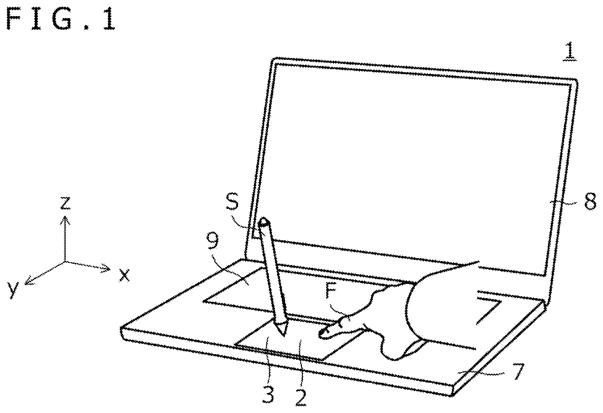
[0032]FIG. 1 depicts a notebook computer 1 including a non-discrete type touch pad 2 according to the present disclosure. Besides the touch pad 2, the notebook computer 1 includes various components typically included in a commercially available notebook computer, such as a housing 7, a display 8, and a keyboard 9 illustrated in FIG. 1, and a CPU 6 illustrated in FIG. 2A to be described later. In the following description, a direction corresponding to a lateral direction as viewed from the user using the notebook computer 1 will be referred to as an x-direction as illustrated in FIG. 1. A direction corresponding to a depth direction will be referred to as a y-direction, and a direction corresponding to a height direction will be referred to as a z-direction.

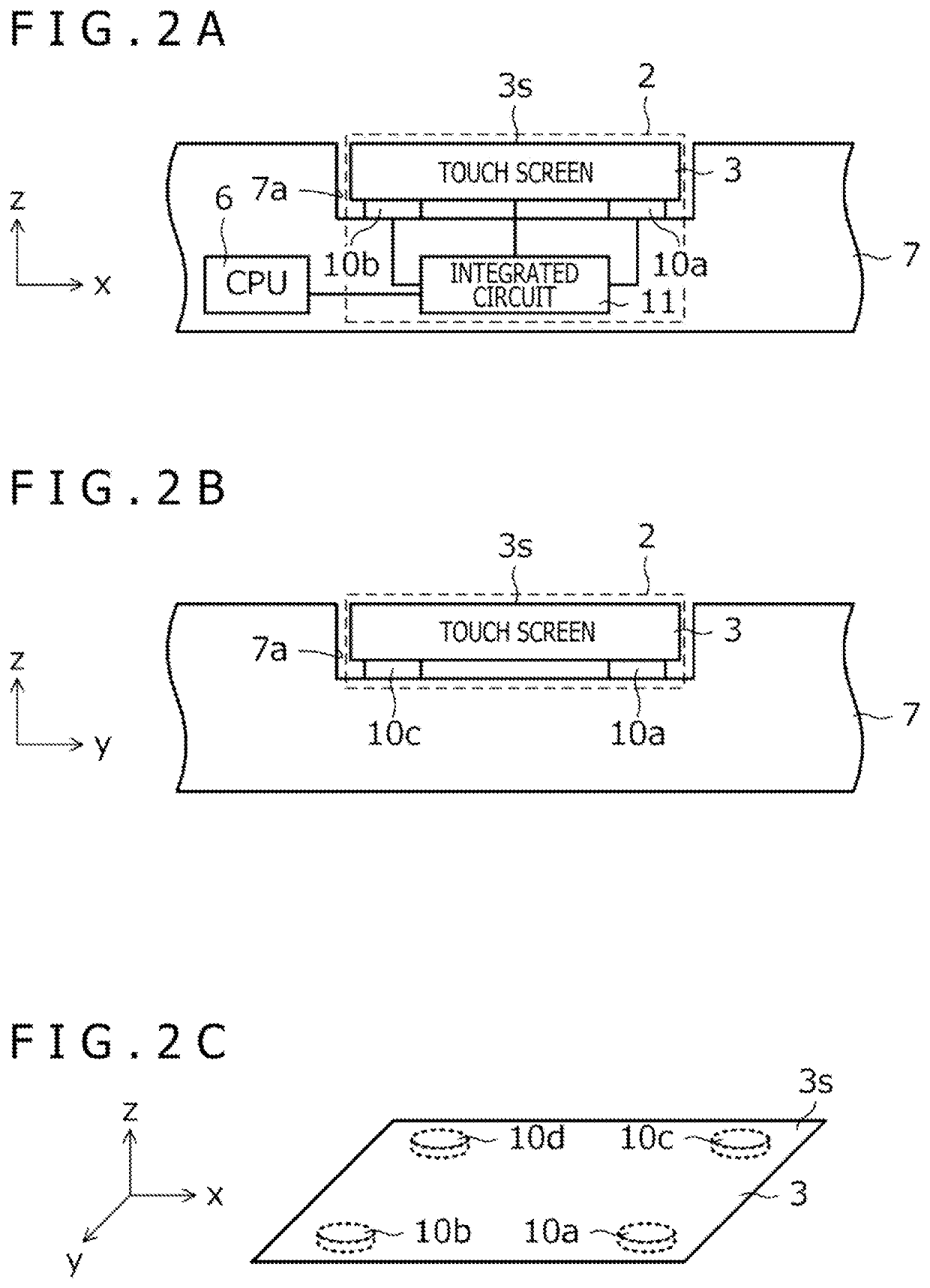
[0033]FIG. 2A depicts a y-direction cross section of the notebook computer 1 near (adjacent to) the touch pad 2, and FIG. 2B depicts an x-direction cross section of the notebook computer 1 near the touch pad 2. FIG. 2C depicts a ...

third embodiment

[0091]FIG. 9A depicts a positional relation, on a plane, among the touch screen 3, the push button switches 15a and 15b, the indication member 16, and the actuator 18 included in the touch pad 2 according to the present embodiment. As illustrated in FIG. 9A, the touch pad 2 according to the present embodiment includes the actuator 18 at a position corresponding to the center of the touch screen 3 in a plan view. The position of the installation of the actuator 18 may be between the push button switches 15a and 15b similarly to the spacer 17 of the

[0092]FIGS. 9B and 9C depict a y-direction cross section of the notebook computer 1 (see FIG. 1) near the actuator 18. As illustrated in FIGS. 9B and 9C, the actuator 18 includes an electromagnet 18a fixed to the housing 7 (more specifically, to the bottom surface of the recess portion 7a illustrated in FIG. 7A and the like) and a permanent magnet 18b fixed to the bottom surface of the touch screen 3. A predetermined gap G is provided betwe...


PUM


Abstract

A touch pad is configured to receive input operations using objects including a finger and a stylus. The touch pad includes a touch screen including a touch detection surface that serves as a button and as a position detection region for detecting positions of the objects. The touch pad includes an integrated circuit having an object detection function of detecting the positions of the objects on the touch detection surface and a button function of detecting a press state of the button based on a force applied to the touch detection surface. The touch pad includes a button function stop unit configured to cause, according to an operation state of the stylus or according to a setting related to an input operation of the stylus, the integrated circuit to stop outputting a button press state value indicative of the press state detected by the button function.

Description

BACKGROUNDTechnical Field[0001]The present disclosure relates to a non-discrete type touch pad and a computer including such a touch pad.Description of the Related Art[0002]A touch pad or a track pad (collectively referred to as a “touch pad”) provided on a notebook computer or the like generally includes a button or a button function for realizing a function equivalent to a right click or left click function of a mouse device. The touch pad is classified into a discrete type or a non-discrete type depending on whether or not the touch screen system is provided separately from the button system.[0003]FIG. 13A depicts a notebook computer 100a including a discrete type touch pad 200a. As illustrated in FIG. 13A, the touch pad 200a of this type includes dedicated buttons 202 and 203 for a click operation realized by a separate system from a touch screen 201.[0004]On the other hand, FIG. 13B depicts a notebook computer 100b including a non-discrete type touch pad 200b. As illustrated in...

Claims


Application Information

Patent Timeline
Patent Type & Authority Applications(United States)
IPC IPC(8): G06F3/0354G06F3/044
CPCG06F3/03547G06F2203/04105G06F3/03545G06F3/0446G06F3/016G06F3/04142G06F3/04162
Inventor KADOWAKI, JUN
Owner WACOM CO LTD
Why Eureka
Try Eureka