Image recording apparatus

a technology of image recording and recording device, which is applied in the direction of power drive mechanism, spacing mechanism, printing, etc., can solve the problems of reducing the allowable current of the power source, difficult to estimate accurate current values of the current, and cost reduction of the power sour

Pending Publication Date: 2021-12-09
BROTHER KOGYO KK
View PDF2 Cites 0 Cited by
  • Summary
  • Abstract
  • Description
  • Claims
  • Application Information

AI Technical Summary

Benefits of technology

[0007]If the currents delivered to the drivable devices are not constant, it may be difficult to estimate accurate current values of the currents. Therefore, it may be necessary to set lower threshold values in consideration of the potential unstableness of the estimated current values. As a result, it may be difficult to drive the plurality of motors utilizing the capacity of the power source efficiently. In this regard, it may be suggested that a limitation current to one of the drivable devices may be variably set based on a current to be delivered to another one of the drivable devices so that a sum of the currents to be distributed to the plurality of drivable devices may be restrained from exceeding the allowable current. In this arrangement, lowering the limitation current unnecessarily may be avoided, and the current to be delivered to the one of the drivable devices may be increased to an extent, in which the current delivered from the power source is closer to the allowable current.
[0009]The present disclosure is advantageous in that an image recording apparatus, in which a plurality of drivable devices may be driven by a power source utilizing a capacity thereof efficiently, and in which abortion of an image recording operation causable by unstable behaviors of the drivable devices due to a limitation current may be avoided, is provided.

Problems solved by technology

However, such cost reduction for the power source may lower an allowable current from the power source.
If the currents delivered to the drivable devices are not constant, it may be difficult to estimate accurate current values of the currents.
As a result, it may be difficult to drive the plurality of motors utilizing the capacity of the power source efficiently.
However, when the limitation current to the one of the drivable devices is variably lowered, behaviors in the one of the drivable devices may be unstable.
If such unstable behaviors of the carriage due to the limitation current are handled as an error, the image recording operation may often be interrupted or aborted even when there is no sheet jam, and even when the operation is resumable.

Method used


Image

  • Image recording apparatus
  • Image recording apparatus
  • Image recording apparatus

Examples


Embodiment Construction

[0018]Hereinafter, the exemplary embodiment according to an aspect of the present disclosure will be described in detail with reference to the accompanying drawings.

[0019]It is noted that various connections may be set forth between elements in the following description. These connections in general and, unless specified otherwise, may be direct or indirect and that this specification is not intended to be limiting in this respect.

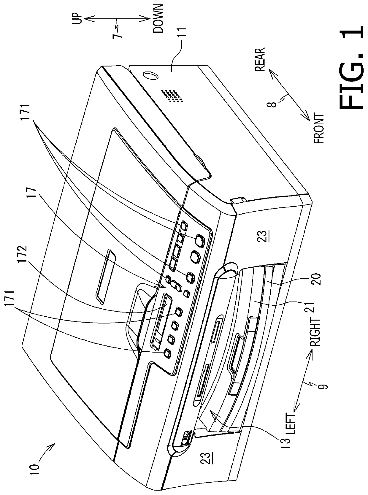
[0020]In the following description, positional relation within the MFP 10 and each part or item included in the MFP 10 will be mentioned on basis of a user's position to ordinarily use the MFP 10 in a usable condition as shown in FIG. 1, with reference to an orientation indicated by the bi-directionally pointing arrows in some of the drawings. For example, in FIG. 1, a vertical axis between an upper side and a lower side in the drawing may be defined as a vertical direction 7. While a side, on which an opening 13 is arranged, is defined as a front side 23,...


PUM


Abstract

An image recording apparatus, having a power source, a drivable device, a head, a motor, a carriage, a sensor, and a controller, is provided. In a recording process, the controller sets a limitation current calculated by subtracting a variable first driving current from an allowable current to the power source, controls the power source to supply the first driving current to the drivable device and simultaneously supply a variable second driving current not exceeding the maximum current to the motor, and when the controller determines, based on a signal output from the sensor, that a behavior of the carriage satisfies an error condition, on condition that the drivable device has completed a targeted conveying action, issue an error alert, and on condition that the drivable device has not completed the targeted conveying action, control the motor to cause the carriage to continue moving without issuing the error alert.

Description

CROSS REFERENCE TO RELATED APPLICATION[0001]This application claims priority under 35 U.S.C. § 119 from Japanese Patent Application No. 2020-097967, filed on Jun. 4, 2020, the entire subject matter of which is incorporated herein by reference.BACKGROUNDTechnical Field[0002]The present disclosure is related to an image recording apparatus capable of recording an image on a sheet.Related Art[0003]An image recording apparatus may often have a plurality of drivable devices, such as motors to drive rollers. From a viewpoint of speeding up an image recording operation, it may be desirable that the drivable devices are driven simultaneously.[0004]For example, an inkjet recording apparatus may record an image on a sheet by discharging ink droplets from nozzles of a head. The inkjet recording apparatus may perform a conveying operation, in which the sheet is conveyed by a predetermined length by rollers, and a recording operation, in which ink droplets are discharged from the head while a ca...

Claims


Application Information

Patent Timeline
Patent Type & Authority Applications(United States)
IPC IPC(8): B41J25/00
CPCB41J25/001B41J23/025B41J19/207
Inventor ARAKAWA, YUTA
Owner BROTHER KOGYO KK
Why Eureka
Try Eureka